
Floor drain position adjusting mechanism and floor drain

A technology for adjusting mechanisms and floor drains, applied in water supply devices, drainage structures, waterway systems, etc.

Pending Publication Date: 2020-02-11
上海远安流体设备科技有限公司
View PDF0 Cites 0 Cited by
  • Summary
  • Abstract
  • Description
  • Claims
  • Application Information

AI Technical Summary

Problems solved by technology

[0004] Therefore, the technical problem to be solved by the present invention is to solve the problem that the existing floor drain cannot realize height adjustment simply and reliably.

Method used


Image

  • Floor drain position adjusting mechanism and floor drain
  • Floor drain position adjusting mechanism and floor drain
  • Floor drain position adjusting mechanism and floor drain

Examples


Embodiment 1

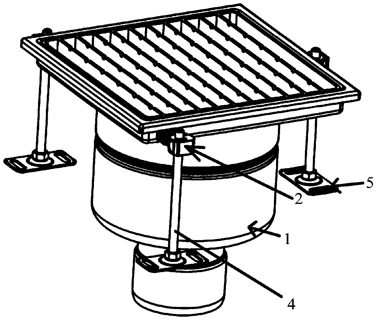
[0038] A floor drain is recorded, such as figure 1 As shown, it includes: a floor drain main body 1, and the floor drain position adjustment mechanism described above can keep the floor drain main body 1 level with the ground surface and ensure the normal drainage of the floor drain main body 1 through the setting of the above-mentioned floor drain position adjustment mechanism.

[0039] This scheme also records a floor drain position adjustment mechanism, such as figure 2 As shown, it includes: a positioning structure 2, which is connected to the main body of the floor drain 1; a support member 4, which is rod-shaped, and the positioning structure 2 is connected to the accommodating cavity for accommodating the main body 1 of the floor drain. The structure 2 is slidably arranged in the length direction of the support 4, and the positioning structure 2 has a positioning state fixedly connected to the support 4, and a sliding state slidingly connected to the support 4. In the ...


PUM


Abstract

The invention discloses a floor drain position adjusting mechanism and a floor drain. Positioning structures connected with a floor drain body and supporting pieces are included. The positioning structures are connected with a containing cavity used for containing the floor drain body. The positioning structures are arranged in the length direction of the supporting pieces in a sliding manner. Thepositioning structures have a positioning state in which the positioning structures are fixedly connected with the supporting pieces and a sliding state in which the positioning structures are in sliding connection with the supporting pieces. The floor drain position adjusting mechanism is provided for solving the problem that an existing floor drain cannot simply and reliably achieve height adjustment.

Description

technical field [0001] The invention relates to the technical field of floor drains, and mainly relates to a floor drain position adjustment mechanism and the floor drain. Background technique [0002] With the continuous advancement of urbanization, more and more people in the world will live in cities and in high-rise buildings in cities. As an important system for the normal operation of buildings, the drainage system is closely related to people's lives. The floor drain is the most critical part of drainage, and its anti-odor performance is very important; only the anti-odor type floor drain can prevent the odor in the sewer from entering the room. Site, its performance directly affects the drainage speed and odor control effect. [0003] In the construction process of the current floor, before installing the floor drain, construction workers need to pre-dig a storage tank for accommodating the floor drain, and then place the floor drain in the storage tank and communi...

Claims


Application Information

Patent Timeline
IPC IPC(8): E03F5/04
CPCE03F5/0407
Inventor 项少聪
Owner 上海远安流体设备科技有限公司
Features
  • Generate Ideas
  • Intellectual Property
  • Life Sciences
  • Materials
  • Tech Scout
  • Unparalleled Data Quality
  • Higher Quality Content
  • 60% Fewer Hallucinations
Learn More