
Light steel protecting window

A steel window protection, light-weight technology, applied in washing devices, fixed grilles, textiles and papermaking, etc., can solve problems such as unfavorable drying or air drying of clothes, small air circulation, and unfavorable drying of clothes, etc. The effect of drying clothes and ventilation, increasing wind flow, and simple structure

Pending Publication Date: 2020-02-11
湖南吉人住工装配式建筑有限公司
View PDF0 Cites 0 Cited by
  • Summary
  • Abstract
  • Description
  • Claims
  • Application Information

AI Technical Summary

Problems solved by technology

[0002] The protective window is a branch of the anti-theft window. Its main function is protection. It is generally installed in buildings with relatively high floors to prevent people from falling from the building. Compared with the anti-theft window, it is relatively exquisite and compact, and has a strong It also has the functions of sun protection, heat preservation, breathability, anti-corrosion, anti-cracking, anti-ultraviolet, etc.; and people usually hang clothes as balconies, which is not conducive to drying clothes in spring and winter, and people usually use them as balconies. The upper end of the protective window for drying clothes is close to the wall, the area of ​​the balcony is small, and the flow rate of the air body is small, which is not conducive to drying or air-drying clothes.

Method used


Image

  • Light steel protecting window
  • Light steel protecting window

Examples


Embodiment Construction

[0013] In order to facilitate the understanding of the present invention, the present invention will be described in more detail below with reference to the drawings and specific embodiments. The drawings show preferred embodiments of the present invention. However, the present invention can be implemented in many different forms and is not limited to the embodiments described in this specification. On the contrary, the purpose of providing these embodiments is to make the understanding of the disclosure of the present invention more thorough and comprehensive.

[0014] It should be noted that when an element is referred to as being "fixed to" another element, it can be directly on the other element or a central element may also exist. When an element is considered to be "connected" to another element, it can be directly connected to the other element or an intermediate element may be present at the same time. The terms "vertical", "horizontal", "left", "right" and similar expr...


PUM


Abstract

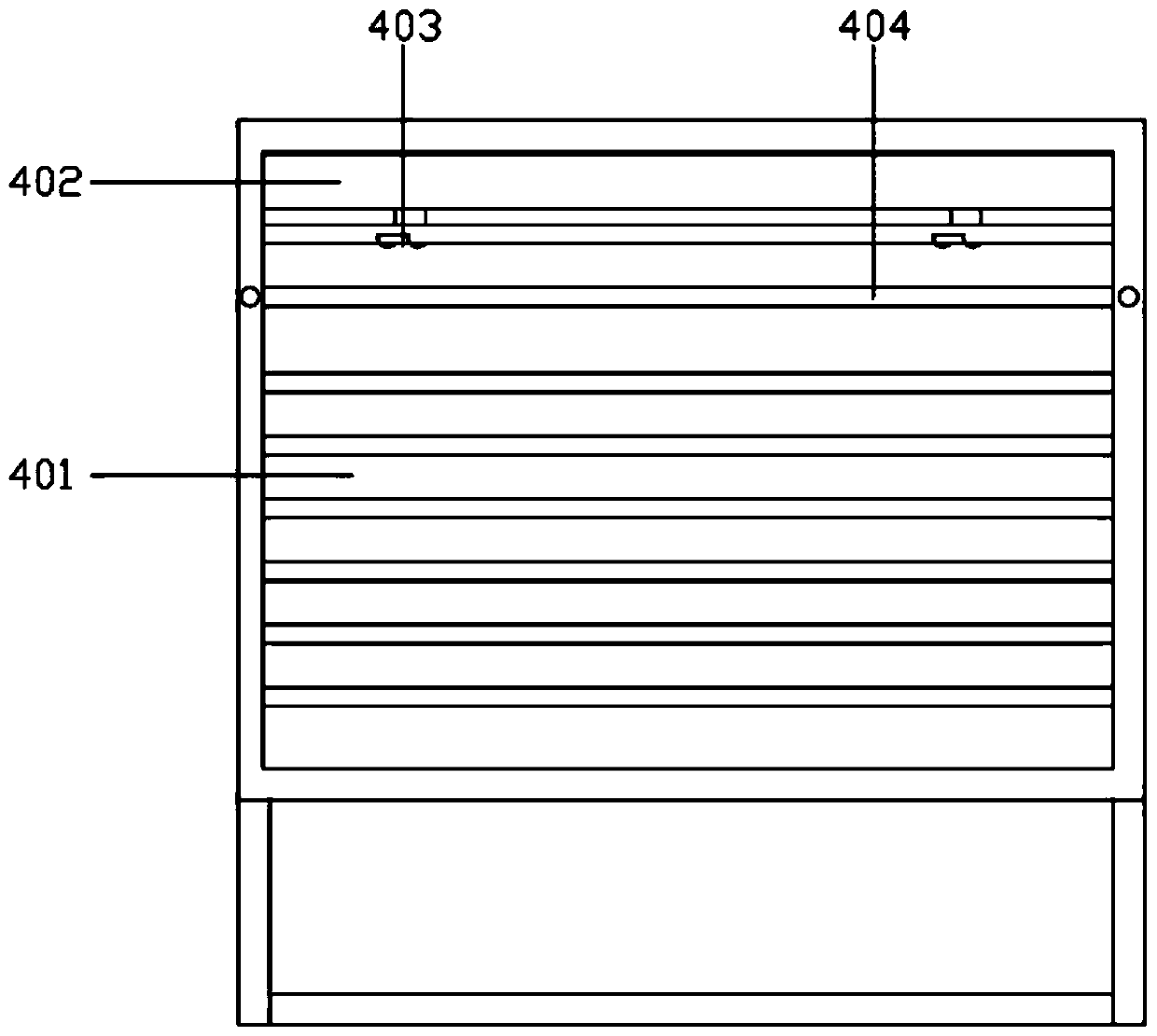
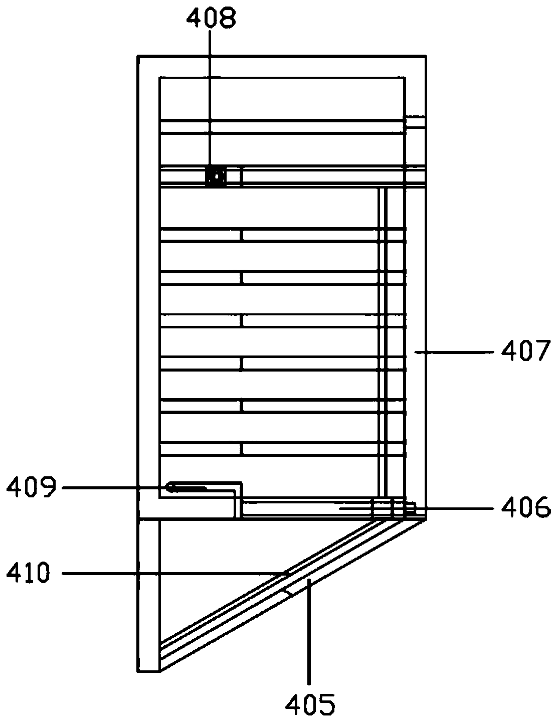
The invention discloses a light steel protecting window. The window comprises a protecting window body, a telescopic sun shield, hooks, a hanging rod, an outer guardrail plate and sliding blocks, thefront plane of the protecting window body is provided with a window, a notch is formed in the corresponding rear plane of the window, the telescopic sun shield is arranged at the upper end of the rearplane notch of the protecting window body through screws, the hooks are arranged on the two sides of the lower end of the telescopic sun shield, handrails of the two sides of the protecting window protection are telescopic rods, the outer guardrail plate is arranged at the protecting window body rear plane notch, and is fastened with the handrails of the two sides in a welding mode, the hanging rod is arranged between the telescopic sun shield and the upper plane of the outer guardrail plate, sliding grooves are formed in the inner sides of the telescopic rods at the upper ends of the handrails at the two sides of the protecting window body, the sliding blocks are matched with the sliding grooves, and a push rod is used for connecting the left side sliding block with the right sliding block. According to the light steel protecting window, the outer guardrail plate can freely move back and forth through a main telescopic rod, the forward extending distance of the protecting window is increased, the space is conveniently and reasonably utilized, and the window is simple in structure and convenient to use.

Description

Technical field [0001] The invention relates to the field of construction technology, in particular to a light steel window guard. Background technique [0002] The protective window is a branch of the anti-theft window. Its main function is protection. It is generally installed in a building with a higher floor to prevent people from falling down. It is relatively beautiful and compact than the anti-theft window. It also has the functions of sun protection, heat preservation, ventilation, anti-corrosion, anti-cracking, anti-ultraviolet rays, etc.; and people usually dry clothes for balcony, which is not conducive to drying clothes in the spring and winter season, and usually people will Because the upper end of the clothes drying window is close to the wall, and the balcony area is small, the air circulation is small, which is not conducive to drying or air drying of the clothes. Summary of the invention [0003] The technical problem to be solved by the present invention is to ...

Claims


Application Information

Patent Timeline
IPC IPC(8): E06B9/01D06F57/12
CPCE06B9/01D06F57/12
Inventor 姚朝辉
Owner 湖南吉人住工装配式建筑有限公司
Learn More