
Pipeline fixing device on building construction scaffold

A technology for building construction and fixing devices, which is applied in the direction of pipe supports, pipes/pipe joints/fittings, mechanical equipment, etc., which can solve the problems of wasting physical strength of workers, falling off of pipe clamps, physical energy consumption and increased difficulty of operation, etc., so as to achieve easy fixing, The effect of reducing difficulty

Inactive Publication Date: 2020-02-11
李小椅
View PDF7 Cites 1 Cited by
  • Summary
  • Abstract
  • Description
  • Claims
  • Application Information

AI Technical Summary

Problems solved by technology

[0002] When laying pipelines in building construction, it is sometimes necessary to route the pipelines on the wall and construct the pipelines through the construction frame. However, when the workers fix the pipelines on the wall, because one end of the pipeline is suspended from the ground, the Pressure will be formed on the pipe clip fixed on the wall, causing the pipe clip to fall off, and when fixing, the worker must drag the pipeline with one hand to secure the pipeline, and fix it with the other hand, but this will Waste the physical strength of workers and increase the labor intensity of workers, especially when fixing thicker pipelines, the pipelines are heavier, physical energy consumption and operation difficulty will also increase

Method used


Image

  • Pipeline fixing device on building construction scaffold
  • Pipeline fixing device on building construction scaffold
  • Pipeline fixing device on building construction scaffold

Examples


Embodiment 1

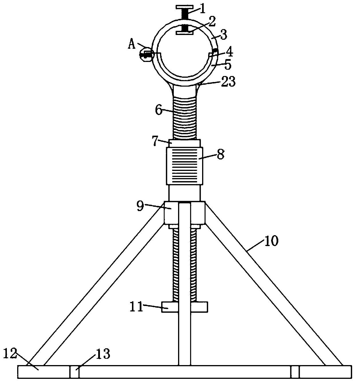
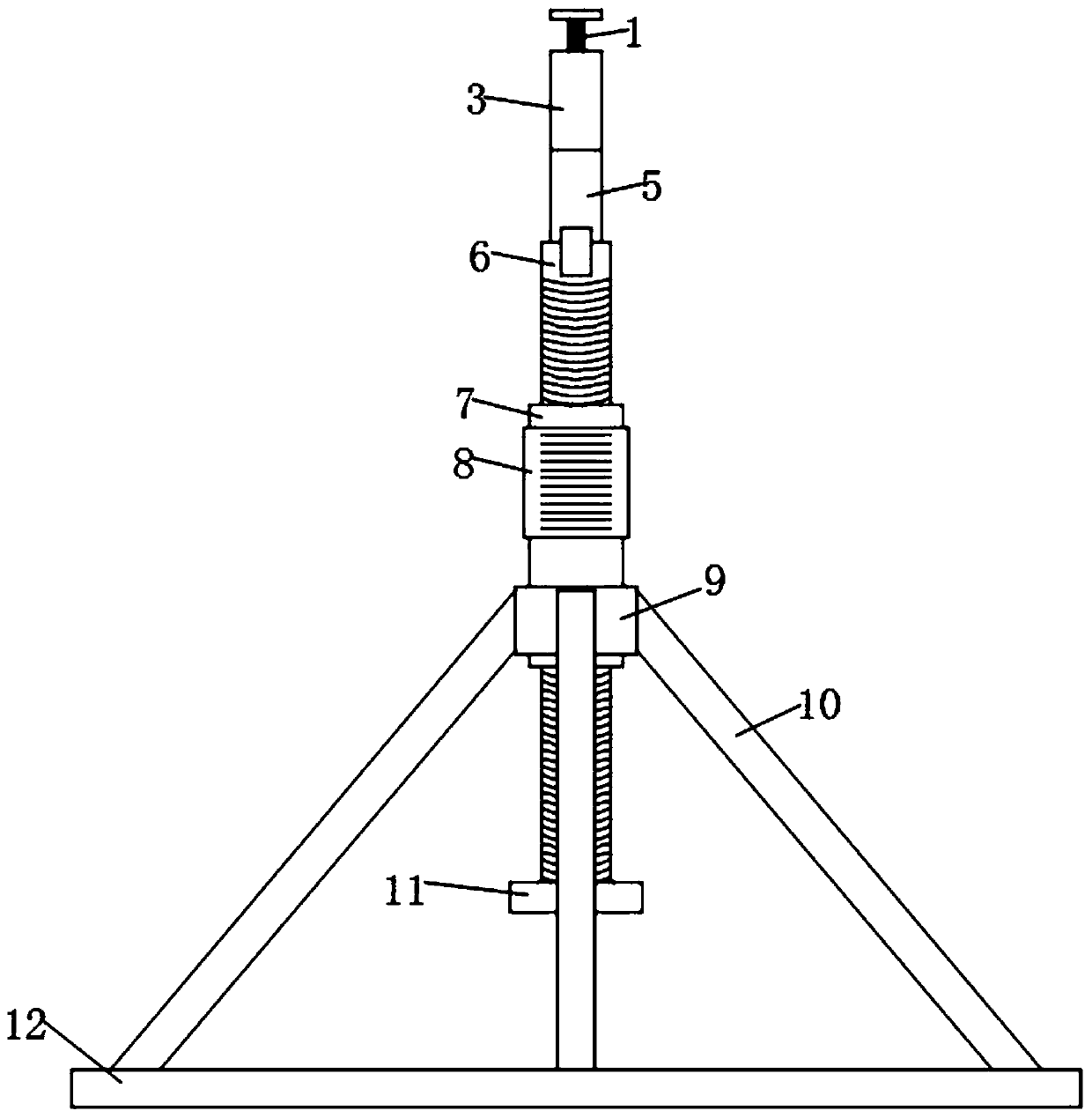
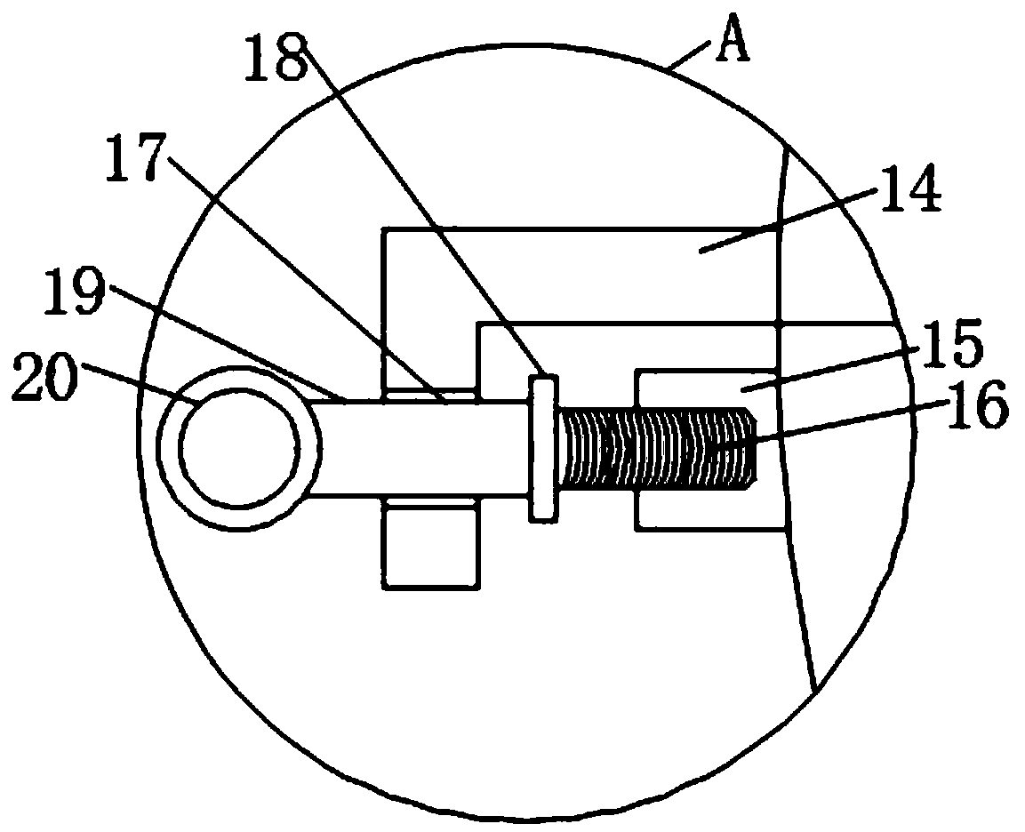
[0021] refer to Figure 1-3 , a pipeline fixing device on a building construction frame, comprising a bottom plate 12, threaded fixing holes 13 are provided around the bottom plate 12, the threaded fixing holes 13 are fixedly connected on the building construction frame by bolts, and inclined supports are fixedly connected around the bottom plate 12 Rod 10, the upper end of the inclined support rod 10 is connected to the support column 6 through the adjustment structure, the upper end of the support column 6 is welded with the lower limit ring 5, and the reinforcement rib 23 is welded between the lower limit ring 5 and the support column 6, the design of the reinforcement rib 23, The fixing effect between the lower limit ring 5 and the support column 6 is enhanced, and the lower limit ring 5 is prevented from falling off.

[0022] One end of the lower limit ring 5 is hinged with an upper limit ring 3, and the other end of the upper limit ring 3 is fixedly connected with an L-s...

Embodiment 2

[0026] refer to Figure 1-3 , as another preferred embodiment of the present invention, the difference from Embodiment 1 is that the adjustment structure includes a bearing 9 fixedly connected to the upper end of the inclined support rod 10, the inner shaft surface of the bearing 9 is fixedly connected with a threaded sleeve 7, and the support column 6 It is provided with external threads, the support column 6 is threadedly connected with the threaded sleeve 7, and the outer side of the threaded sleeve 7 is fixedly bonded with a gripping sleeve 8, and the outer side of the gripping sleeve 8 is provided with anti-slip lines, and the gripping sleeve 8 is rotated by one hand, and a hand holds The support column 6 will drive the handle sleeve 8 to rotate on the support column 6, thereby adjusting the height of the support column 6, so as to ensure that when the pipeline is installed, the lower limit ring 5 plays a role in supporting the pipeline, so that the pipeline Being on the ...

Embodiment 3

[0028] refer to Figure 4 , as another preferred embodiment of the present invention, the difference from Embodiment 2 is that the handle cover 8 includes a sweat-absorbing layer 21, the inner ring of the sweat-absorbing layer 21 is fixedly bonded with an elastic layer 22, and the elastic layer 22 is fixedly bonded to the threaded sleeve 7 , the sweat-absorbing layer 21 is made of polymer water-absorbing resin, and the elastic layer 22 is made of butadiene rubber material. By the design of the sweat-absorbing layer 21, when the worker rotates the handle 8, it is convenient to absorb the sweat on the worker's hand and prevent sweat The effect of grasping is affected, and the design of the elastic layer 22 enhances the comfort when grasping.


PUM


Abstract

The invention relates to the technical field of building construction, in particular to a pipeline fixing device on a building construction scaffold. The pipeline fixing device comprises a bottom plate, oblique supporting rods are fixedly connected to the periphery of the bottom plate, the upper ends of the oblique supporting rods are connected with a supporting column through an adjusting structure, a lower limiting ring is welded to the upper end of the supporting column, an upper limiting ring is hinged to one end of the lower limiting ring, and the other end of the upper limiting ring is fixedly connected with an L-shaped block. A through hole is formed in the L-shaped block, a fixing column is inserted into the through hole, one end of the fixing column is fixedly connected with a ring buckle, and the other end of the ring buckle is fixedly connected with a threaded fixing rod. A connecting base is fixedly connected to the lower limiting ring, the threaded fixing rod is in threaded connection with the connecting base, the middle of the upper limiting ring is in threaded through connection with the fastening screw, and a fixing block is fixed to the lower end of the fastening screw. By means of the pipeline fixing device, the difficulty generated when workers arrange pipelines is reduced, and the pipeline fixing device has the advantage that the pipeline fixing effect is facilitated.

Description

technical field [0001] The invention relates to the technical field of building construction, in particular to a pipeline fixing device on a building construction frame. Background technique [0002] When laying pipelines in building construction, it is sometimes necessary to route the pipelines on the wall and construct the pipelines through the construction frame. However, when the workers fix the pipelines on the wall, because one end of the pipeline is suspended from the ground, the Pressure will be formed on the pipe clip fixed on the wall, causing the pipe clip to fall off, and when fixing, the worker must drag the pipeline with one hand to secure the pipeline, and fix it with the other hand, but this will The physical strength of the workers is wasted, and the labor intensity of the workers is increased. Especially when fixing thicker pipelines, the pipelines are heavier, and the physical energy consumption and operation difficulty will also increase. Contents of th...

Claims


Application Information

Patent Timeline
Patent Type & Authority Applications(China)
IPC IPC(8): F16L3/20F16L3/10
CPCF16L3/105F16L3/20
Inventor 李小椅
Owner 李小椅
Learn More