

Current sensor
A current sensor and current technology, applied in the direction of only measuring current, voltage/current isolation, measuring current/voltage, etc., can solve problems such as inability to offset the impact, and achieve low-cost effects
- Summary
- Abstract
- Description
- Claims
- Application Information
AI Technical Summary
Problems solved by technology
Method used
Image

Examples
no. 1 example
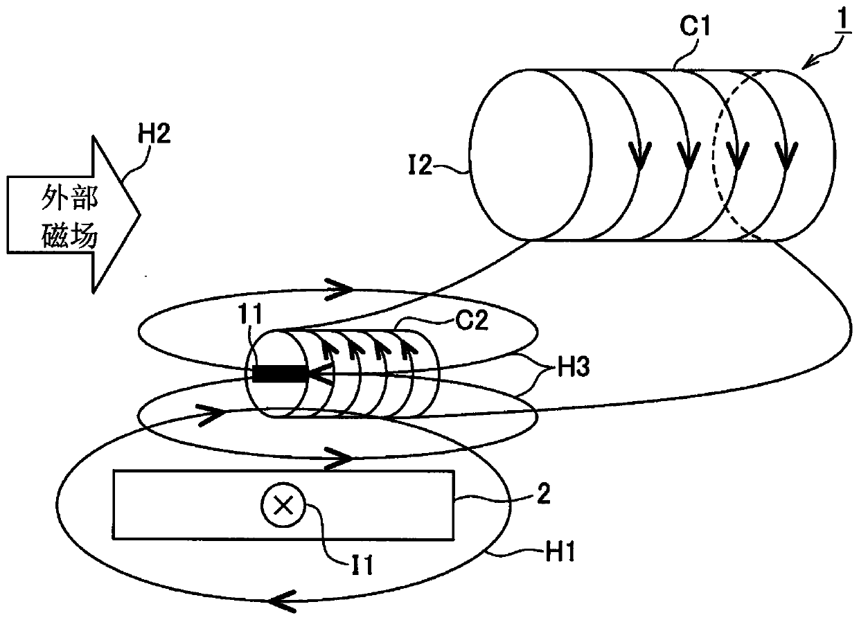
[0029] Below, will refer to figure 1 A first embodiment of the present invention will be described. figure 1 The illustrated current sensor 1 is a sensor configured to detect a current I1 flowing through a bus bar (measurement object) 2 . In the figure, a current I1 flows in the bus bar 2 in a direction perpendicular to the paper surface, and a magnetic field H1 is generated by this current I1. The magnetic field H1 is generated around an axis corresponding to the flow direction of I1 (ie, the direction perpendicular to the paper surface).
[0030] The current sensor 1 includes a magnetic field detection element 11, a first coil C1, and a second coil C2. The magnetic field detection element 11 is an element that outputs a voltage corresponding to the magnitude of the magnetic field, and is arranged around the bus bar 2 (a range where the magnetic field H1 enters or penetrates).
[0031] The output of the magnetic field detection element 11 may be affected by an external mag...
no. 2 example
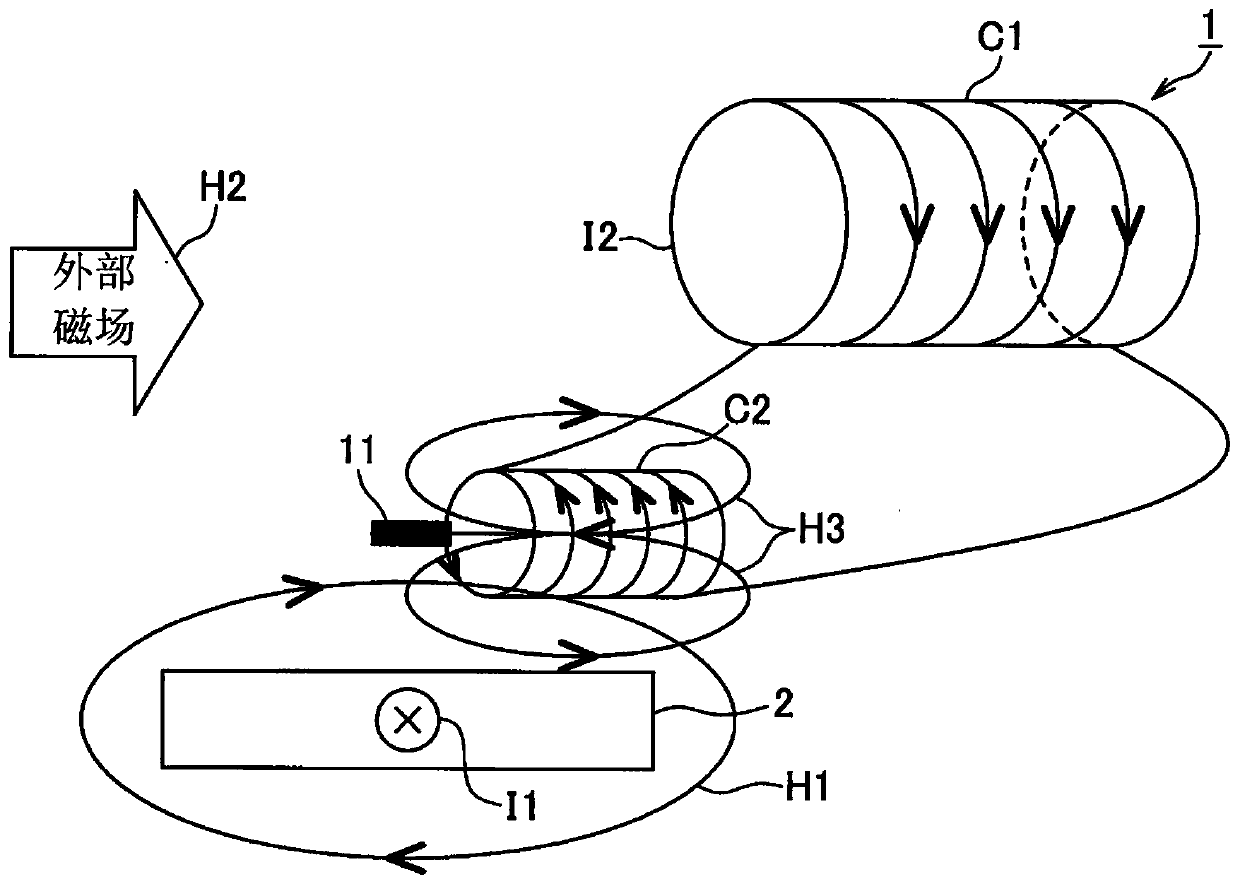
[0043] Next, refer to figure 2 A second embodiment of the present invention will be described. The difference between the second embodiment and the first embodiment mainly lies in the arrangement position of the magnetic field detection element 11 . In the second embodiment, the magnetic field detection element 11 is arranged outside the second coil C2 along the magnetic field generated by the second coil C2. Furthermore, in the second embodiment, the magnetic field detection element 11 and the second coil C2 are arranged oppositely along the axial direction of the second coil C2 with a space therebetween. Notice, figure 2 The direction of the magnetic field H3 in the arrangement position of the second embodiment shown is the same as the direction of the magnetic field H3 inside the second coil C2.
[0044] As in the case of the first embodiment, in this case, an induced current I2 is generated in the first coil C1 based on a change in the external magnetic field H2, and ...
no. 3 example
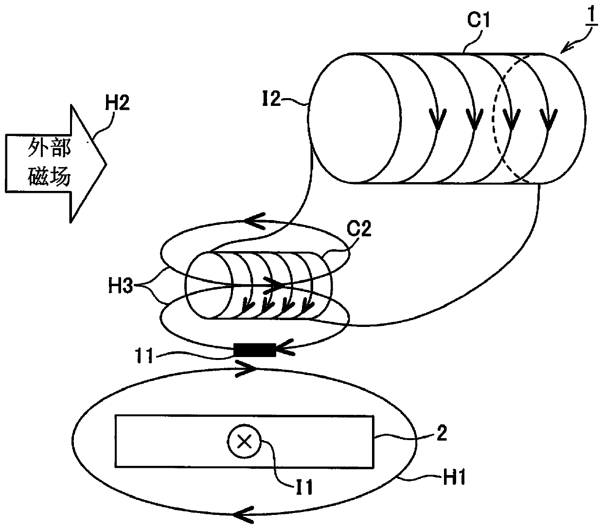
[0046] Next, refer to image 3 A third embodiment of the present invention will be described. The difference between the third embodiment and the first embodiment mainly lies in the arrangement positions of the magnetic field detection elements 11 . In the third embodiment, the magnetic field detection element 11 is arranged outside the second coil C2 along the magnetic field generated by the second coil C2. Furthermore, in the third embodiment, the magnetic field detection element 11 and the second coil C2 are arranged oppositely along the radial direction of the second coil C2 with a space therebetween. Notice, image 3 The direction of the magnetic field H3 in the arrangement position of the third embodiment shown is opposite to the direction of the magnetic field H3 inside the second coil C2.
[0047] Thus, unlike the first and second embodiments, in the third embodiment, the winding directions of the first coil C1 and the second coil C2 are the same.
[0048] Next, the ...
PUM
 Abstract
Description
Claims
Application Information