Waveguide slot antenna plate conveying device

A technology of waveguide crack antenna and conveying device, which is applied in the direction of grinding driving device, grinding slide plate, grinding machine tool parts, etc., can solve the problems that the antenna plate cannot be guaranteed to have the same polishing accuracy and low production efficiency, and achieve improved stability , Improve production efficiency, improve the effect of stability

Active Publication Date: 2021-11-30
CHENGDU NANJIAO TECH
View PDF6 Cites 0 Cited by
  • Summary
  • Abstract
  • Description
  • Claims
  • Application Information

AI Technical Summary

Problems solved by technology

[0002] In the prior art, the waveguide slot antenna is generally a flat plate structure, and the plate used to install the antenna cannot be used directly. In order to improve the accuracy of the antenna, the surface of the purchased antenna plate needs to be polished before it can be used. Now the antenna plate is polished. Generally, the antenna plate is manually transported to the polishing device, and then the antenna plate is manually taken out. This kind of production efficiency is very low. At the same time, because the manual pushing of the antenna plate cannot guarantee the same polishing accuracy of the antenna plate, it is necessary. Antenna plate to device in polishing unit without interference between the two

Method used


Image

  • Waveguide slot antenna plate conveying device
  • Waveguide slot antenna plate conveying device
  • Waveguide slot antenna plate conveying device

Examples


Embodiment approach

[0036] Specific embodiments described as follows:

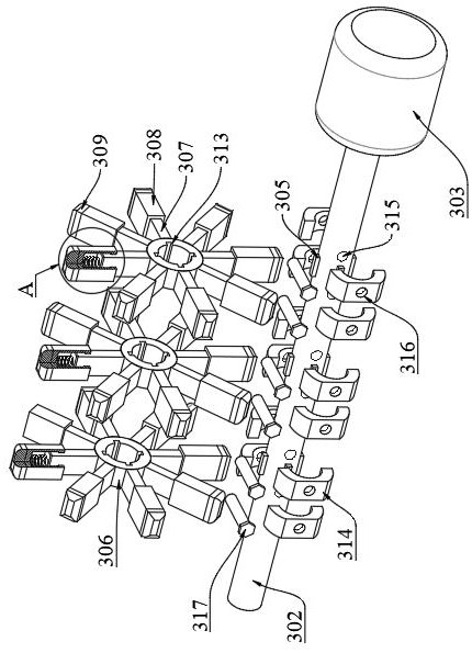
[0037] First select the antenna sheet sizes adapted according to the belt 105, so that projection 106 may be stuck in the belt 105, then block 306 is connected through the second shaft 302 is provided, and the second shaft pin 302 of the key 305 and the connecting block 306 with the keyways 313, and the connecting block 306 disposed on each side of two limiting blocks 314 and 317 are connected with the two stopper pin 314, the connecting block 306 is fixed;

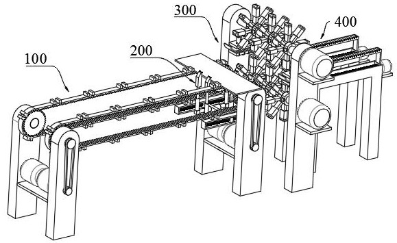
[0038] After the antenna plate is placed in a set of protrusions 106, to start the first motor 104, first drive shaft 103 rotates, following the rotation of the gear 102 connected to a first shaft 103, is rotated to follow the conveyor belt 105, the conveyance of the sheet antenna, antenna when the sheet conveying end of the conveyor 105 to start a first telescopic rod 206, drive block 207 is moved upward clip, clamp block clamp antenna plate 207, clamp plate 207 side surfac...


PUM


Abstract

The invention discloses a waveguide slot antenna plate conveying device. The device is arranged at one side of a polishing device and comprises a first conveying mechanism, a pushing mechanism, a second conveying mechanism, a third conveying mechanism, a clamping mechanism, a first polishing mechanism, a second polishing mechanism and a third polishing mechanism, wherein the first polishing mechanism, the second polishing mechanism and the third polishing mechanism are arranged in sequence; and the first polishing mechanism comprises a plurality of polishing assemblies, and each polishing assembly comprises two symmetrically-arranged polishing units. The first conveying mechanism is arranged between two polishing units, the first conveying mechanism comprises two first conveying assemblies which are symmetrically arranged and used for bearing an antenna plate, and the pushing mechanism is arranged at one end of the first conveying mechanism, located between the two first conveying assemblies and used for transferring the antenna plate to the second conveying mechanism; the second conveying mechanism is arranged between the first conveying mechanism and the second polishing mechanism, and the third conveying mechanism is arranged at one side of the second polishing mechanism and located below the third polishing mechanism, so that the production efficiency is greatly improved, and the production precision is guaranteed; and the conveying stability is improved.

Description

Technical field [0001] The present invention relates to the field of production and processing technology waveguide slot antenna associated with one particular waveguide slot antenna sheet conveying device. Background technique [0002] In the prior art, generally flat plate waveguide slot antenna configuration, while the board for mounting the antenna can not be directly used to improve the accuracy of the antenna, the antenna sheet surface after purchasing needs to use after polishing, polishing sheet now antenna when the antenna is generally employed manually transporting the sheet to the polishing apparatus, and then manually remove the antenna sheet, so that production efficiency is low, while the antenna due to manual push plate polishing accuracy can not be guaranteed the same antenna sheet, it can be a need for an automatic transmission the antenna device of the sheet material to the polishing apparatus, while no interference therebetween. Inventive content [0003] For ...

Claims


Application Information

Patent Timeline
Patent Type & Authority Applications(China)
IPC IPC(8): B24B29/08B24B41/00B24B41/06B24B41/02B24B47/04
CPCB24B29/08B24B41/005B24B41/06B24B41/02B24B47/04
Inventor 李平王梅
Owner CHENGDU NANJIAO TECH
Why Eureka
Try Eureka