
Filter S parameter dephasing loading method and system, medium and equipment

A filter and phase technology, applied in the field of filter modeling and simulation design, can solve problems such as unreasonable S parameters, differences in optimization results, and filter optimization design that affect the accuracy of filter coupling matrix extraction, and achieve high calculation accuracy , the effect of algorithm stability

Active Publication Date: 2020-02-11
SOUTHWEST CHINA RES INST OF ELECTRONICS EQUIP
View PDF4 Cites 4 Cited by
  • Summary
  • Abstract
  • Description
  • Claims
  • Application Information

AI Technical Summary

Problems solved by technology

[0002] At present, in the process of filter modeling parameter extraction, the original S parameters include the dispersion effect of the input and output high-order modes and the phase shift of the test system and the port itself, which will cause the reference phase plane to be inconsistent with the ideal circuit model of the filter, thus affecting the filter Accuracy of Filter Coupling Matrix Extraction and Further Filter Optimal Design
[0003] In the prior art, the loading phase removal amount is determined by curve polynomial fitting of the phase shift and time delay of the actual loading physical structure, but since the actual loading phase value is very small, the extraction accuracy of this method is not ideal
In addition, in the prior art, there is an optimization method to iteratively adjust the phase shift, so that the calculated value after removing the phase shift is close to the real value. difference, that is, there is an unreasonable difference between the S-parameters of the admittance parameter transformation and the S-parameters of the filter coupling matrix transformation under the same deloading situation, so it is impossible to achieve better dephasing loading

Method used


Image

  • Filter S parameter dephasing loading method and system, medium and equipment
  • Filter S parameter dephasing loading method and system, medium and equipment
  • Filter S parameter dephasing loading method and system, medium and equipment

Examples


Embodiment 1

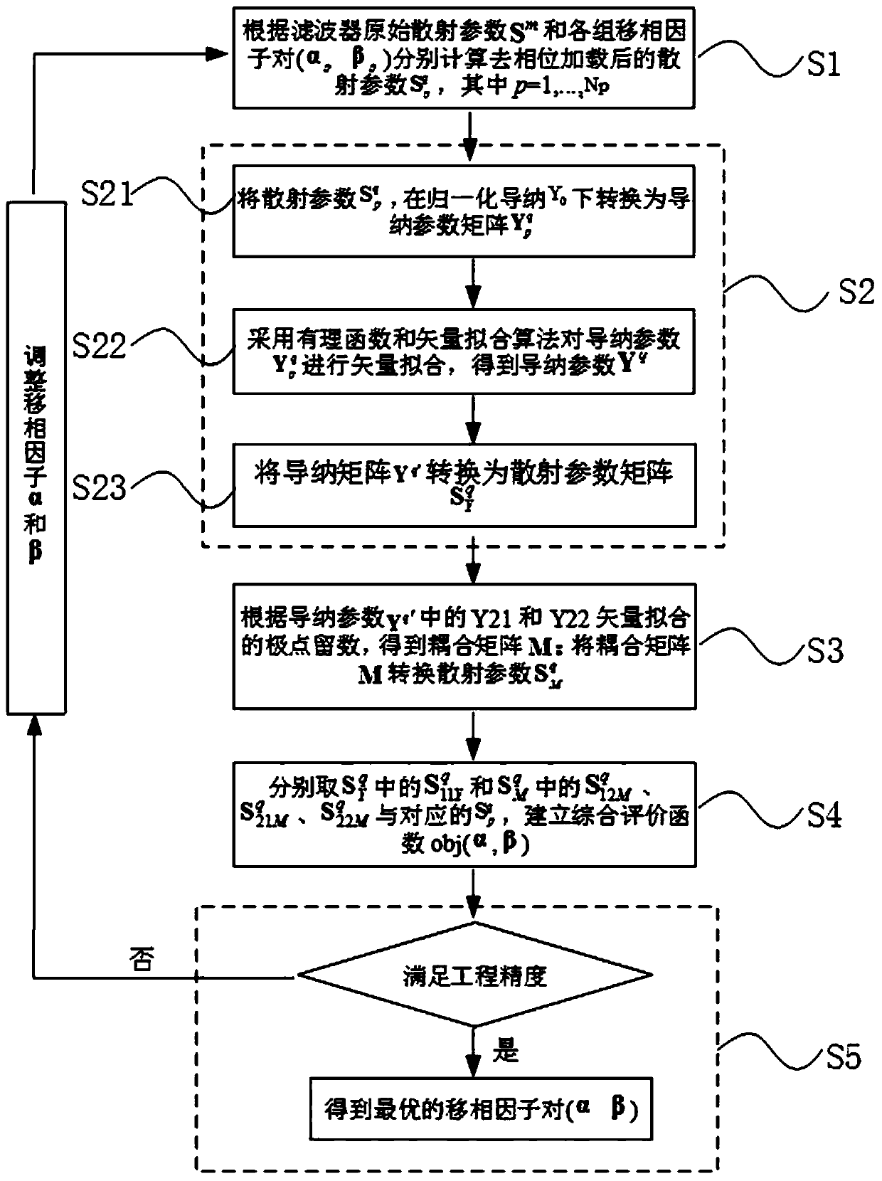
[0050] Embodiment one: method flow process of the present invention, refer to figure 1 ,include:

[0051] Step S1, according to the original scattering parameter S of the filter m and each group of phase-shifting factor pairs (α p beta p ) respectively calculate the first scattering parameter after dephasing loading where p=1,...,Np;

[0052] Step S2, the first scattering parameter In the normalized admittance parameter Y 0 Down conversion to the first admittance parameter And adopt rational function and vector fitting algorithm to described first admittance parameter Perform vector fitting to obtain the second admittance parameter Y q′ ; The second admittance parameter Y q′ Converted to the second scattering parameter

[0053] In this embodiment, the specific process of step S2 is:

[0054] Step S21, the first scattering parameter In the normalized admittance parameter Y 0 Next, use the following formula to convert to the first admittance parameter

[0...

Embodiment 2

[0067] Embodiment two: on the basis of embodiment one, each group of phase-shifting factor pairs (α p beta p ) is obtained by randomly initializing the phase-shifting factors α and β within the range values ​​respectively set by the phase-shifting factors α and β; wherein, α is a loading constant item, including the high-order mode introduced by the input and output ports; β is Loading the equivalent electrical length of the transmission line, the transmission line including the input and output ports introduces a phase shift.

[0068] In this embodiment, the limited initialization range of α is π·[0.9,1.1], and the initialization range of β is π·[0,0.25]. In addition, the phase shift factors α and β include the input and output phases of the filter The loading parameters are specifically:

[0069]

[0070]

[0071] in, is the frequency-independent constant term introduced by the high-order mode, θ is the equivalent electrical length introduced by the transmission li...

Embodiment 3

[0073] Embodiment three, on the basis of embodiment one and two, according to S m and each group of phase-shifting factor pairs (α p beta p ), respectively use the following formula to calculate the corresponding first scattering parameter after dephasing loading

[0074]

[0075] in, Indicates the original scattering parameter of the filter; f s Indicates the sampling frequency.

[0076] It should be understood that when the filter is a symmetric reciprocal structure, the phase shift factors of the four S parameters are respectively equal, that is, when calculating the phase removal amount, as long as a certain S parameter is accurately loaded, the remaining S parameters are at the same The phase-shifting factors are also accurately removed under the treatment of phase-shifting factors; otherwise, the phase-shifting factors of each S-parameter are independently optimized variables to be calculated during the optimization process.


PUM


Abstract

The invention provides a filter S parameter dephasing loading method and a system, a medium and equipment, and relates to the technical field of filter modeling simulation design. The method comprisesthe steps that a second admittance parameter Yq'is converted into a second scattering parameter, a coupling matrix M is converted into a third scattering parameter, and a comprehensive evaluation function obj (alpha beta) is established according to the second scattering parameter and the third scattering parameter; and a phase shift factor pair (alpha beta) closest to a theoretical value is found according to the comprehensive evaluation function obj (alpha beta). According to the method, a stable dephasing loading method is established, and an intelligent optimization algorithm is combined,so that a globally optimal solution of a phase shift factor during modeling parameter extraction of the microwave filter is found. The original S parameter dephasing loading meets the multi-attributeconstraint condition of filter extraction modeling, so that the algorithm is more stable, and the calculation precision is higher.

Description

technical field [0001] The present invention relates to the technical field of filter modeling and simulation design, and more specifically, to a filter S parameter dephasing loading method, system, medium and equipment. Background technique [0002] At present, in the process of filter modeling parameter extraction, the original S parameters include the dispersion effect of the input and output high-order modes and the phase shift of the test system and the port itself, which will cause the reference phase plane to be inconsistent with the ideal circuit model of the filter, thus affecting the filter The accuracy of filter coupling matrix extraction and further filter optimization design. [0003] In the prior art, the loading phase removal amount is determined by curve polynomial fitting of the phase shift and time delay of the actual loading physical structure, but since the actual loading phase value is very small, the extraction accuracy of this method is not ideal. In ...

Claims


Application Information

Patent Timeline
IPC IPC(8): G06F30/20G06F111/04G06N3/12
CPCG06N3/126Y02E40/40
Inventor 高阳张晏铭廖翱马宁米添李阳阳金长林
Owner SOUTHWEST CHINA RES INST OF ELECTRONICS EQUIP
Learn More