Display system for planar design

A graphic design and display system technology, applied in applications, home appliances, display stands, etc., can solve problems such as poor layering and dynamic effects, difficulty in arousing the interest of viewers, and rigid display methods, achieving strong practicability and a sense of hierarchy. and dynamic effect

Inactive Publication Date: 2020-02-14
CHIZHOU UNIV
View PDF5 Cites 2 Cited by
  • Summary
  • Abstract
  • Description
  • Claims
  • Application Information

AI Technical Summary

Problems solved by technology

[0002] At present, the display of graphic design works mostly still adopts the traditional display method, using a glass cabinet or a fixed position on the wall to display the work. This display method is very rigid, and the layering and dynamic effects of the display are poor. interest the viewer

Method used


Image

  • Display system for planar design
  • Display system for planar design
  • Display system for planar design

Examples


Embodiment 1

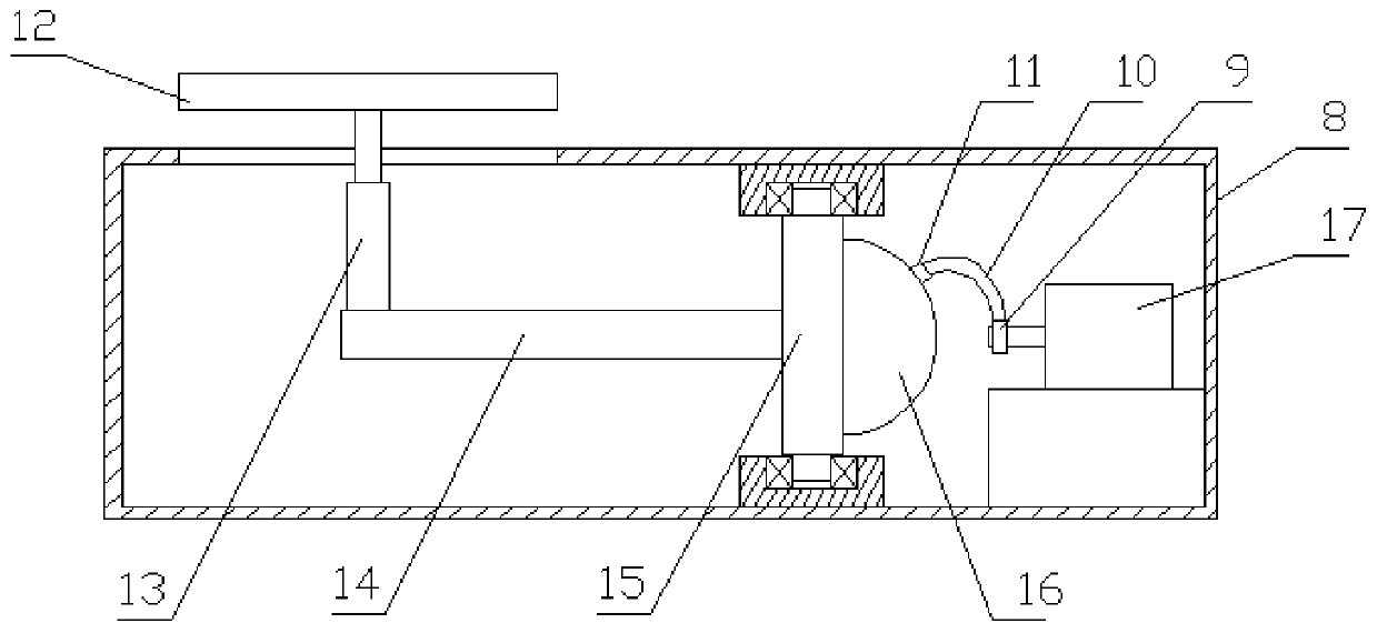
[0020] like figure 1 As shown, a display system for graphic design provided by the present invention includes a box body 8 used as a support, and a plurality of motors 17 used as a driving power source are arranged inside the box body 8, and the output of the motors 17 A cylindrical body 9 is fitted on the shaft, and the cylindrical body 9 is fixedly connected with the output shaft of the motor 17 .

[0021] The outer wall of cylinder body 9 is fixedly connected with one end of curved rod 10, and the other end of described curved rod 10 is fixed with slider 11; The side of described slider 11 is provided with vertically placed rotating shaft 15, and described rotating shaft 15 passes The bearing is mounted on the inner wall of the box body 8 , and a cam 16 is provided on the circumference of the rotating shaft 15 .

[0022] like Figure 5 and Image 6 As shown, the cam 16 includes a semicircular plate body 1601, the circumferential plane end of the semicircular plate body 1...

Embodiment 2

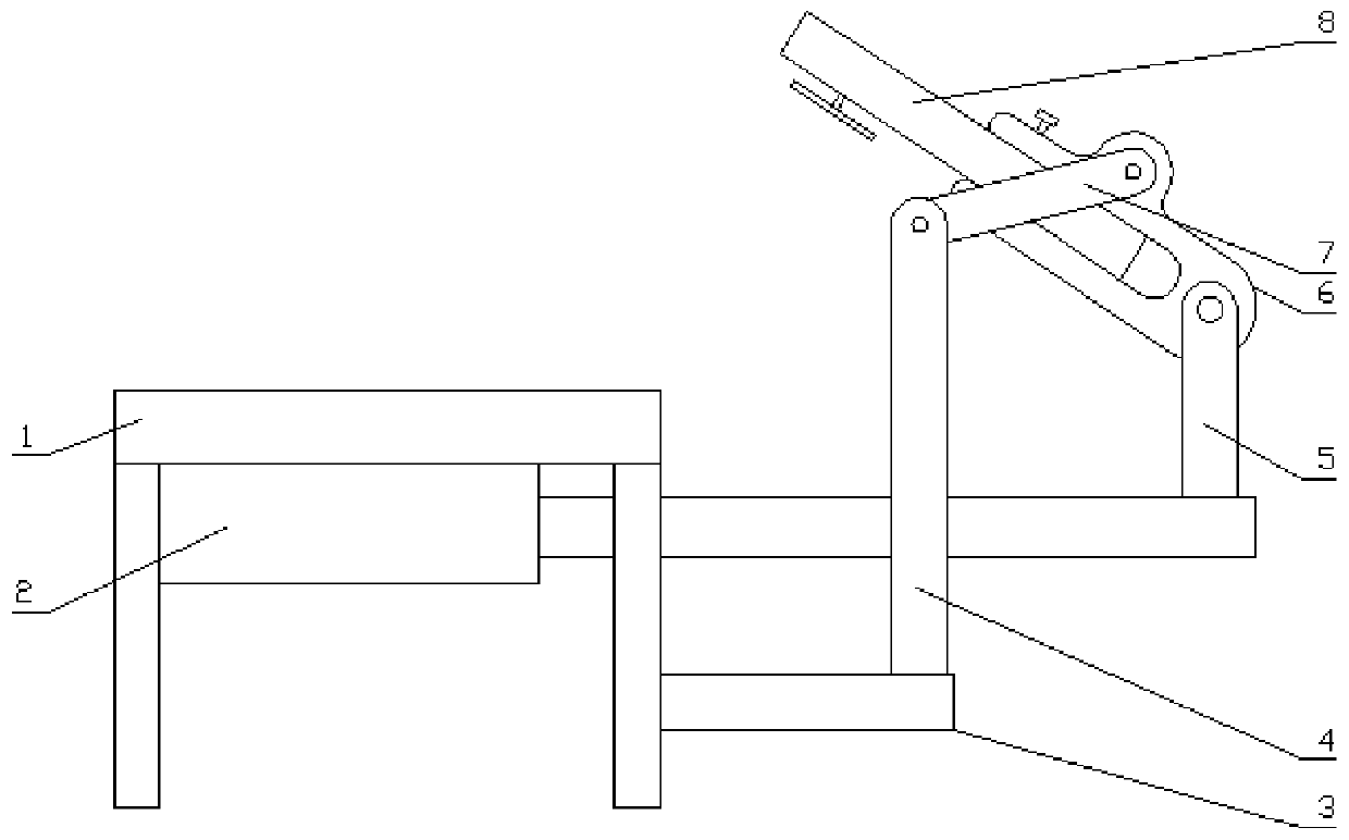
[0028] As a further improvement on the basis of Example 1, such as figure 2 As shown, the two sides of the box body 8 are symmetrically provided with clamping and clamping structures 6 for clamping the box body 8 .

[0029] like image 3 and Figure 4 As shown, the snap-in clamping structure 6 includes plate body one, plate body two and plate body three which are sequentially fixedly connected to form a U-shaped opening snap-in structure, and the middle section of the plate body one is fixed with connecting lugs, so The first board is provided with at least one fastening device 1 for fixing the position of the box body 8 , and the third board is provided with at least one fastening device 2 for fixing the position of the clamping structure 6 .

[0030] The above clamping structure 6 is used for clamping the box body 8, and it is convenient to fix the position of the box body 8 on the wall or other exhibition stands for exhibition.

Embodiment 3

[0032] As a further improvement on the basis of Example 2, such as figure 2 As shown, the plate body 2 is hinged with one end of the pole 2 5, and the other end of the pole 2 5 is vertically fixed at the end of the piston rod of the hydraulic cylinder 2, and the hydraulic cylinder 2 is fixed under the table top of the table body 1. . The table legs of the table body 1 are also fixed with a horizontally placed pole three 3, and the end of the pole three 3 away from the table body 1 is vertically fixed with pole four 4, and the pole four 4 deviates from the pole three. The end of 3 is hinged with one end of connecting rod 7, and the other end of said connecting rod 7 is hinged with lug.

[0033] When the length of the piston rod of the hydraulic cylinder 2 changes, the surface inclination angle of the box body 8 can be changed around the hinged end of the lug and the connecting rod 7, and the inclination angle change of the visible surface of the box body 8 can be realized to ...


PUM


Abstract

The invention relates to a display system for planar design. The display system comprises a box body; a plurality of motors are arranged in the box body; barrel bodies are fixed to output shafts of the motors in a sleeving manner; the outer circumference of each barrel body fixedly connected with one end of a curved rod; a sliding block is fixed to the other end of each curved rod; the side edge of each sliding block is provided with a vertically placed rotating shaft; each rotating shaft is erected on the inner wall of the box body through a bearing; a cam is arranged in the circumferential direction of each rotating shaft; each cam comprises a semicircular plate body; the plane end of each semicircular plate body in the circumferential direction is fixedly connected with each rotating shaft; a sliding groove is formed in the curved surface end of each semicircular plate body in the circumferential direction; a sliding block is clamped in each sliding groove; a horizontally placed transmission rod body is further fixed in the circumferential direction of each rotating shaft; a supporting rod I is vertically fixed to one end, deviating from each rotating shaft, of each transmissionrod body; and a fixing device used for placing a planar design work is arranged at the tail end, deviating from each transmission rod body, of each supporting rod I after the supporting rod I penetrates out of the box body. According to the display system, the layering sense and the dynamic effect in display are good, the interest of a viewer can be quickly attracted, and the display system is high in practicability and worthy of popularization.

Description

technical field [0001] The invention belongs to the technical field of display for graphic design, and in particular relates to a display system for graphic design. Background technique [0002] At present, the display of graphic design works mostly still adopts the traditional display method, using a glass cabinet or a fixed position on the wall to display the work. hold the viewer's interest. Contents of the invention [0003] In view of this, the present invention provides a graphic design display system in order to solve the deficiencies in the prior art. [0004] Technical scheme of the present invention is: [0005] A display system for graphic design, comprising a box body, a plurality of motors are arranged inside the box body, a cylinder body is fitted and fixed on the output shaft of the motor body, and the outer circumference of the cylinder body is fixedly connected with one end of a curved rod , the other end of the crank rod is fixed with a slider; the sid...

Claims


Application Information

Patent Timeline
IPC IPC(8): A47F7/14A47F5/025A47F5/10A47F5/12
CPCA47F5/025A47F5/10A47F5/12A47F7/142A47F7/143
Inventor 冯鹤
Owner CHIZHOU UNIV
Why Eureka
Try Eureka