Coating proportioning and stirring equipment
A technology for stirring equipment and coatings, which is applied to mixer accessories, mixers with rotating stirring devices, mixers, etc., which can solve the problems of being unable to control the amount of two coatings, unable to ensure the removal of impurities, and unable to ensure safety, etc.
- Summary
- Abstract
- Description
- Claims
- Application Information
AI Technical Summary
Problems solved by technology
Method used
Image
Examples
specific Embodiment approach 1
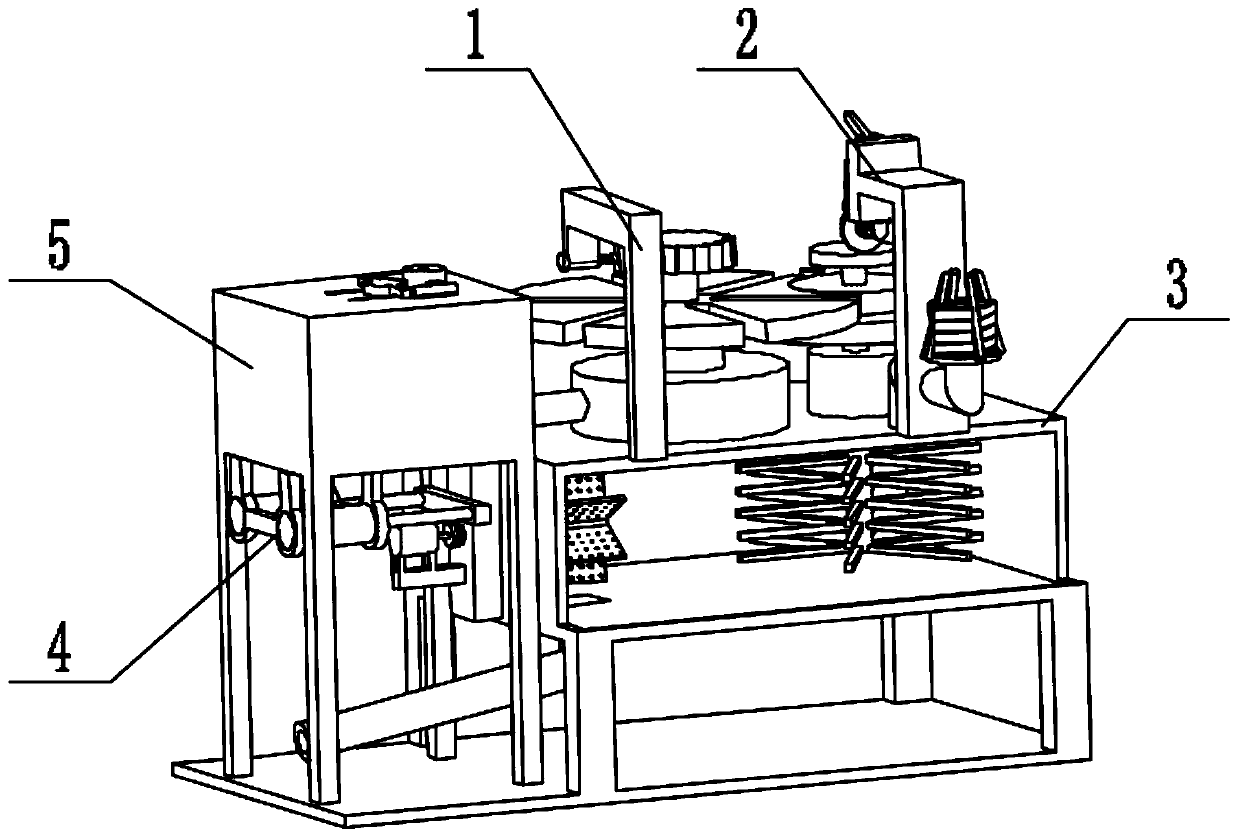
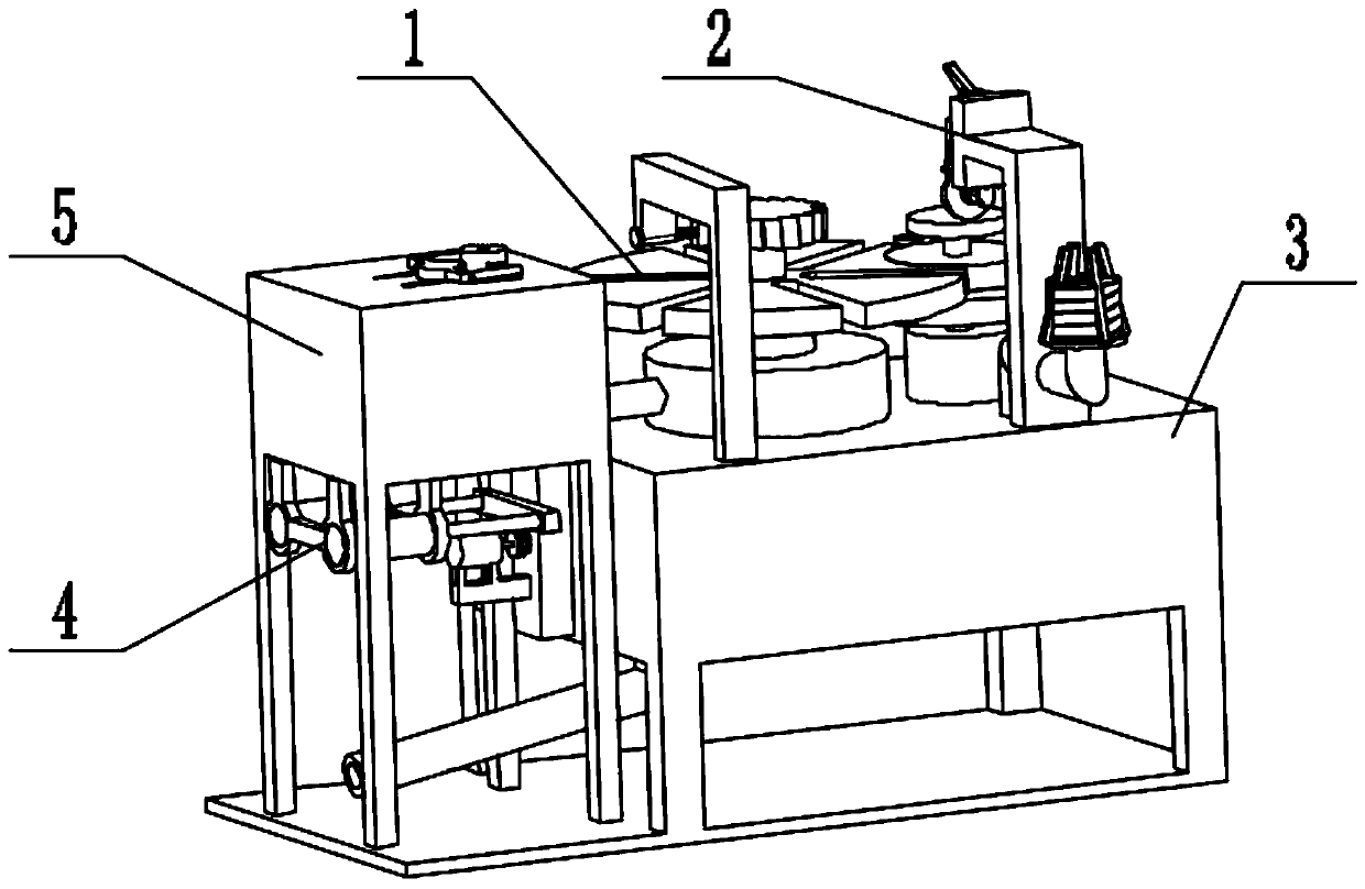
[0041] Combine below figure 1 , figure 2 , image 3 , Figure 4 , Figure 5 , Figure 6 , Figure 7 , Figure 8 , Figure 9 , Figure 10 , Figure 11 , Figure 12 , Figure 13 , Figure 14 , Figure 15 , Figure 16 , Figure 17 , Figure 18 , Figure 19 , Figure 20 , Figure 21 , Figure 22 , Figure 23 , Figure 24 To illustrate this embodiment, the present invention relates to a stirring device, more specifically a paint mixing device, including a mixing mechanism 1, a safety drive mechanism 2, a fuselage mechanism 3, a filter mechanism 4, and a paint replenishment mechanism 5. The equipment can mix the paint in proportion, the equipment can adjust the stirring speed, the equipment can ensure the safety of the mixing process, the equipment can filter while unloading, and the equipment can control whether to replenish the paint.
[0042] The proportioning stirring mechanism 1 is connected with the fuselage mechanism 3, the proportioning stirring mechan...
specific Embodiment approach 2
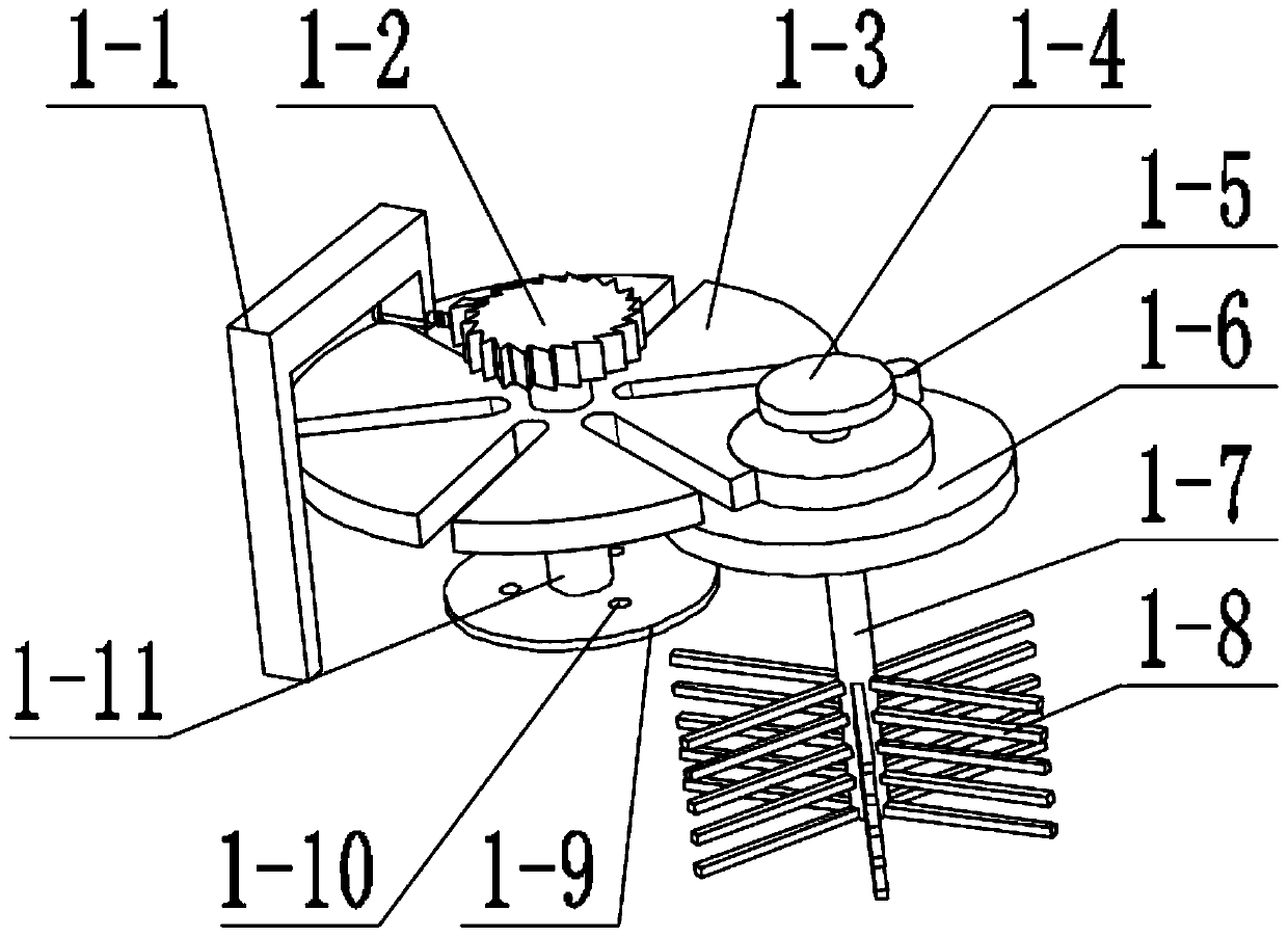
[0044] Combine below figure 1 , figure 2 , image 3 , Figure 4 , Figure 5 , Figure 6 , Figure 7 , Figure 8 , Figure 9 , Figure 10 , Figure 11 , Figure 12 , Figure 13 , Figure 14 , Figure 15 , Figure 16 , Figure 17 , Figure 18 , Figure 19 , Figure 20 , Figure 21 , Figure 22 , Figure 23 , Figure 24 Describe this embodiment, this embodiment will further explain the first embodiment, the proportioning stirring mechanism 1 includes a limit mechanism 1-1, a ratchet 1-2, a grooved disc 1-3, a friction disc 1-4, a convex Head 1-5, rotating step disk 1-6, stirring shaft 1-7, stirring blade 1-8, bottom rotating disk 1-9, opening 1-10, connecting shaft 1-11, limit mechanism 1-1 and The ratchet 1-2 is matched, the ratchet 1-2 is connected with the connecting shaft 1-11, the connecting shaft 1-11 is connected with the bottom rotating disc 1-9, the opening 1-10 is opened on the bottom rotating disc 1-9, and the friction disc 1-4 is connected with...
specific Embodiment approach 3
[0046] Combine below figure 1 , figure 2 , image 3 , Figure 4 , Figure 5 , Figure 6 , Figure 7 , Figure 8 , Figure 9 , Figure 10 , Figure 11 , Figure 12 , Figure 13 , Figure 14 , Figure 15 , Figure 16 , Figure 17 , Figure 18 , Figure 19 , Figure 20 , Figure 21 , Figure 22 , Figure 23 , Figure 24Describe this embodiment, this embodiment will further explain the first embodiment, the safety drive mechanism 2 includes a support mechanism 2-1, a safety pin mechanism 2-2, a bending arm mechanism 2-3, a hydraulic cylinder 2-4, a sliding Seat 2-5, step groove 2-6, linkage arm mechanism 2-7, driving mechanism 2-8, rotating shaft mechanism 2-9, rotating friction wheel mechanism 2-10, support mechanism 2-1 and safety pin mechanism 2- 2 are connected, the safety pin mechanism 2-2 cooperates with the curved arm mechanism 2-3, the curved arm mechanism 2-3 is hinged with the support mechanism 2-1, the hydraulic cylinder 2-4 is connected with the ...
PUM
 Abstract
Description
Claims
Application Information
 - R&D
- Intellectual Property
- Life Sciences
- Materials
- Tech Scout
- Unparalleled Data Quality
- Higher Quality Content
- 60% Fewer Hallucinations
Browse by: Latest US Patents, China's latest patents, Technical Efficacy Thesaurus, Application Domain, Technology Topic, Popular Technical Reports.
© 2025 PatSnap. All rights reserved.Legal|Privacy policy|Modern Slavery Act Transparency Statement|Sitemap|About US| Contact US: help@patsnap.com


