
One-driving-multi-station synchronous turbine transmission mechanism

A transmission mechanism and multi-station technology, applied in the direction of manufacturing tools, grinding workpiece supports, grinding drive devices, etc., can solve the problems of equipment station expansion, wiring difficulties, and complicated control programs

Pending Publication Date: 2020-02-14
深圳市精速五金机械有限公司
View PDF0 Cites 2 Cited by
  • Summary
  • Abstract
  • Description
  • Claims
  • Application Information

AI Technical Summary

Problems solved by technology

[0003] The polishing machine used to process the mobile phone shell adopts multi-motor linkage and multi-axis, and each station is driven by an independent motor. The motors need to be controlled synchronously, wiring is difficult, and the control program is complicated, which restricts the expansion of the number of equipment stations.

Method used


Image

  • One-driving-multi-station synchronous turbine transmission mechanism
  • One-driving-multi-station synchronous turbine transmission mechanism
  • One-driving-multi-station synchronous turbine transmission mechanism

Examples


Embodiment Construction

[0020] Specific embodiments of the present invention will be described in detail below in conjunction with the accompanying drawings. It should be understood that the specific embodiments described here are only used to illustrate and explain the present invention, and are not intended to limit the present invention.

[0021] It should be noted that when an element is referred to as being “fixed on” or “disposed on” another element, it may be directly on the other element or there may be an intervening element at the same time. When an element is referred to as being "connected to" another element, it can be directly connected to the other element or intervening elements may also be present.

[0022] In the present invention, unless stated otherwise, the used orientation words such as "up, down, left, right" usually refer to figure 1 Up and down and left and right are shown. "Inner and outer" refer to the inner and outer on the specific outline. "Far and near" refer to far ...


PUM


Abstract

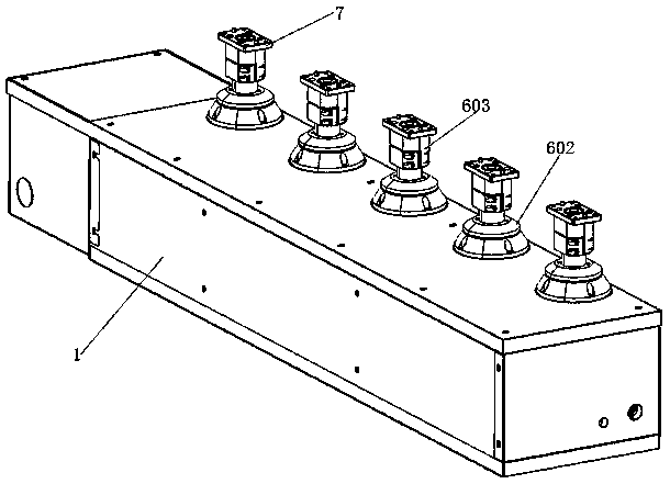
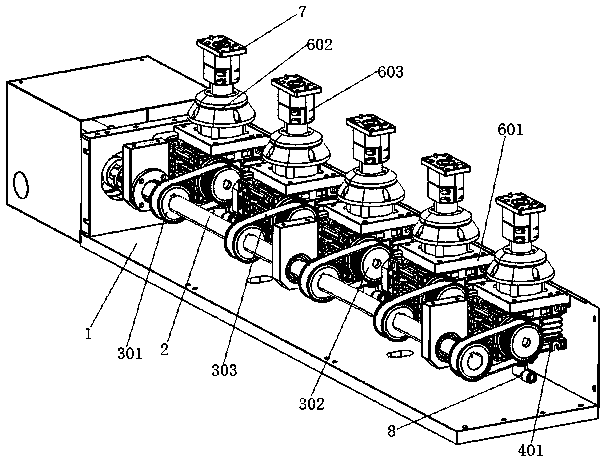
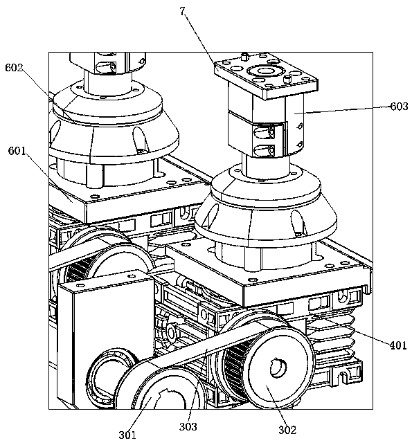
The invention relates to the field of polishing equipment, and discloses a one-driving-multi-station synchronous turbine transmission mechanism. The one-driving-multi-station synchronous turbine transmission mechanism comprises a machine box, a transmission shaft is arranged in the machine box, wherein a motor is arranged on the side face of the machine box and is in transmission connection with the transmission shaft; the transmission shaft is connected with a plurality of belt transmission pairs; a turbine worm base is arranged on one side of each belt transmission pair; a turbine and a wormare rotatably arranged in each turbine worm base; one end of each worm is connected with the corresponding belt transmission pair; the middle of each worm is in engaged connection with the corresponding turbine; the turbines are horizontally arranged; mounting holes are formed in the middles of the turbines; rotating shafts are arranged in the mounting holes in a sleeved manner; air ways are formed in the rotating shafts along the central axis; jig plates are arranged at the upper ends of the rotating shafts; and high-speed rotating connectors are arranged at the lower ends of the rotating shafts. The transmission shaft, the belt transmission pairs and the worms are matched to drive the turbines, the turbines drive the rotating shafts and the jig plates, and synchronous running of a plurality of jig plates is achieved.

Description

technical field [0001] The invention relates to the field of polishing equipment, in particular to a one-drag multi-station synchronous turbine transmission mechanism. Background technique [0002] The surface of the finished mobile phone case must be free from spots, scratches and other defects that affect the appearance. During the whole production process of the mobile phone casing, it is inevitable that there will be more or less bad defects such as scratches. During the production process, a polishing machine will be used for polishing treatment to eliminate spots and scratches on the surface of the mobile phone case, so that the product meets the factory requirements. [0003] The polishing machine used to process mobile phone casings uses multi-motor linkage and multi-axis, and each station is driven by an independent motor. Synchronous control of the motors is required, wiring is difficult, and the control program is complicated, which restricts the expansion of the...

Claims


Application Information

Patent Timeline
Patent Type & Authority Applications(China)
IPC IPC(8): B24B55/06B24B29/02B24B27/00B24B47/12B24B41/06
CPCB24B55/06B24B29/02B24B27/0023B24B47/12B24B41/06
Inventor 赵志荣
Owner 深圳市精速五金机械有限公司
Learn More