
Central air conditioner heat energy recycling device and method

A heat recovery and central air-conditioning technology, which is applied in energy recovery systems for ventilation and heating, heating methods, air-conditioning systems, etc., can solve problems affecting indoor air quality, inconvenience, etc., to reduce labor intensity, increase costs, and reduce placement Quantity effect

Inactive Publication Date: 2021-08-24
深圳超能数通能源技术有限公司
View PDF0 Cites 0 Cited by
  • Summary
  • Abstract
  • Description
  • Claims
  • Application Information

AI Technical Summary

Problems solved by technology

[0003] At present, the central air-conditioning heat recovery device in the market can only re-absorb the hot air and reheat it and then discharge it. At this time, the dust in the room will be sucked into the device together. Over time, a large amount of dust will accumulate in the device, which requires workers to clean it manually, which is very uncomfortable. Convenience, even dust and hot air will be discharged together, which will greatly affect the indoor air quality, so a central air-conditioning heat recovery device and method are proposed to solve the above-mentioned problems

Method used


Image

  • Central air conditioner heat energy recycling device and method
  • Central air conditioner heat energy recycling device and method
  • Central air conditioner heat energy recycling device and method

Examples


Embodiment 1

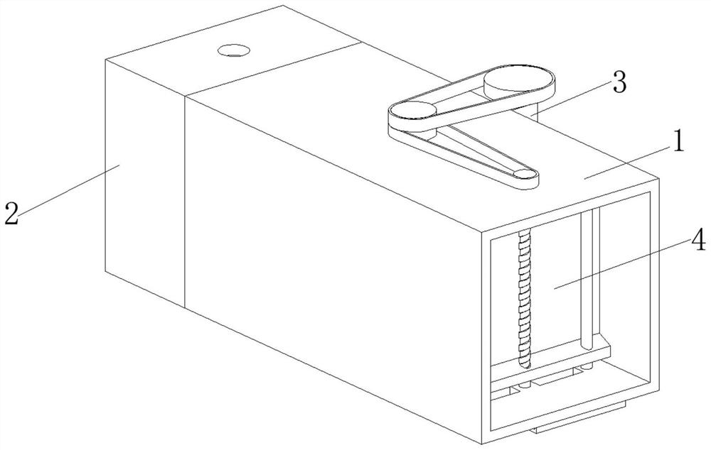
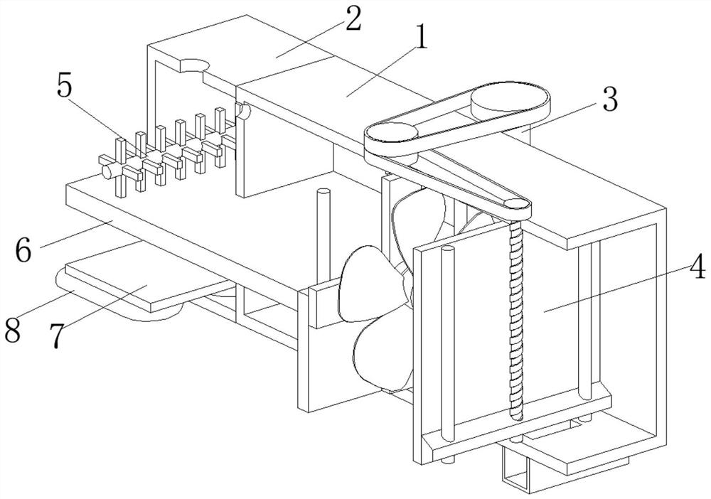
[0038] A central air-conditioning heat recovery device and method, such as Figure 1-Figure 7 As shown, the box body 1 is included, the left side of the box body 1 is welded with an auxiliary box 2, the rear portion of the box body 1 is provided with a transmission mechanism 3, the inside of the box body 1 is provided with a cleaning mechanism 4, and the inside of the auxiliary box 2 is provided with a The processing mechanism 5, the inner wall of the box body 1 and the auxiliary box 2 are welded with a partition plate 6, the inner wall of the auxiliary box 2 is welded with a splint 7, and the left side of the box body 1 is communicated with a ventilation pipe 8.

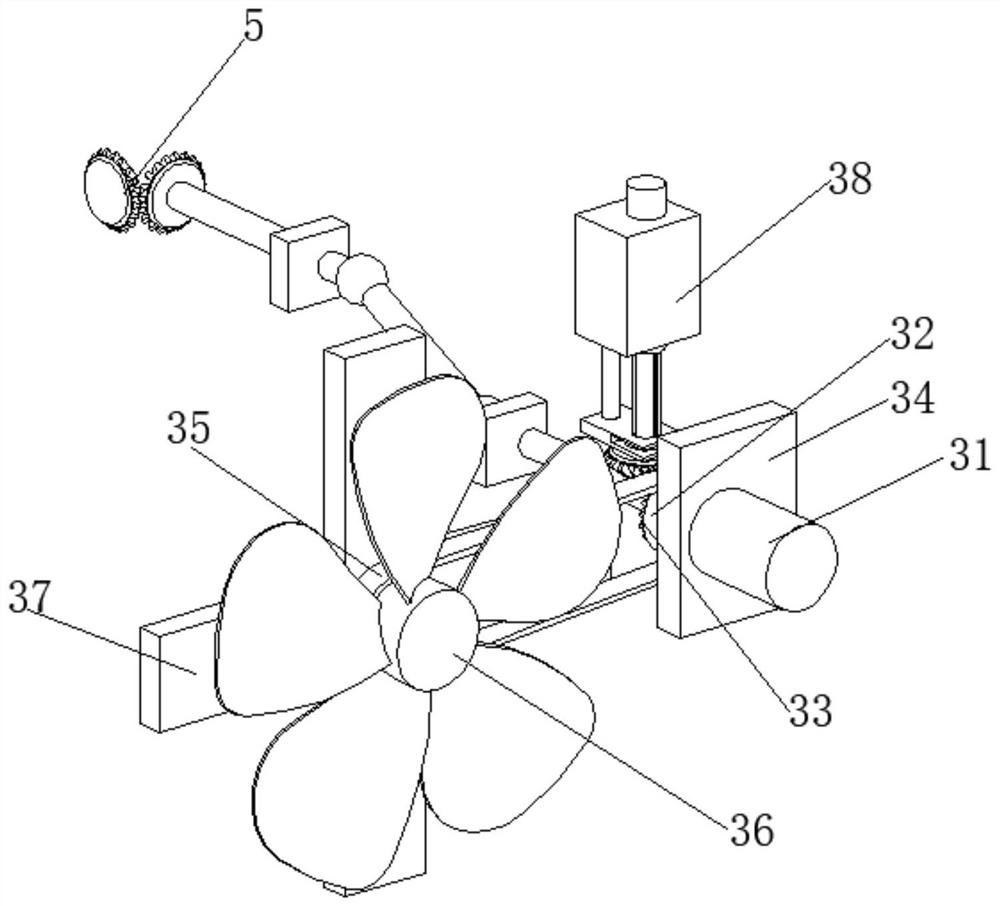
[0039]In this embodiment, the transmission mechanism 3 includes a motor 31, the output end of the motor 31 is welded with a No. 1 pulley 32, and the shaft center of the No. 1 pulley 32 is welded with a No. 1 bevel gear 33, and the left end of the motor 31 is connected with a support plate 34 by bolts. , the surface ...

Embodiment 2

[0045] like Figure 4-Figure 7 As shown, the axis of the large belt pulley 41 is welded and fixed to the top of the telescopic column 382, ​​the surfaces of the No. 1 screw 44 and the No. 2 screw 45 are connected with the inner wall of the box body 1 in rotation, and the baffle plate 47 is located between the partition plate 6 and the support bar. Between 37, the surfaces of the baffle plate 47 and the scraper 49 are slidingly connected with the inner wall of the box body 1, and the left side of the scraper 49 is in contact with the right side of the filter plate 48.

[0046] It is worth noting that the processing mechanism 5 includes a fixed plate 51, the inner wall of the fixed plate 51 is rotatably connected with a transmission rod 52, the left end of the transmission rod 52 is welded with a No. 3 bevel gear 53, and the surface of the No. 3 bevel gear 53 is engaged with a No. 4 cone Gear 54, No. 4 bevel gear 54 is welded with rotating shaft 55 at the axial center, the surfa...


PUM


Abstract

The invention relates to the technical field of central air conditioners, and discloses a central air conditioner heat energy recycling device and method.The central air conditioner heat energy recycling device comprises a box body, wherein an auxiliary box is welded to the left side of the box body, a transmission mechanism is arranged on the rear portion of the box body, a cleaning mechanism is arranged in the box body, a processing mechanism is arranged in the auxiliary box, and partition plates are welded to the inner walls of the box body and the auxiliary box. A clamping plate is welded to the inner wall of the auxiliary box, and the left side of the box body communicates with a ventilation pipe. According to the central air conditioner heat energy recycling device and method, the sucked hot air can be filtered automatically and the filtered dust can be cleaned and collected through a cleaning mechanism. Therefore, manual cleaning by workers is not needed, the labor intensity of the workers is reduced, dust and hot air are prevented from being discharged together, the indoor air quality is greatly improved, the hot air discharged again can be purified through the treatment mechanism, harmful gas in the hot air is reduced, purification liquid is stirred, and the reaction efficiency is improved.

Description

technical field [0001] The invention relates to the technical field of central air-conditioning, in particular to a central air-conditioning heat recovery device and method. Background technique [0002] The central air-conditioning system is composed of one or more cold and heat source systems and multiple air-conditioning systems. This system is different from the traditional refrigerant air-conditioning system, which concentrates on processing air to meet comfort requirements. It adopts the principle of liquid vaporization refrigeration to provide air conditioning systems. The required cooling capacity is used to offset the heat load of the indoor environment; the heating system provides the required heat for the air conditioning system to offset the cooling and heating load of the indoor environment. [0003] At present, the central air-conditioning heat recovery device in the market can only re-absorb the hot air and reheat it and then discharge it. At this time, the du...

Claims


Application Information

Patent Timeline
Patent Type & Authority Applications(China)
IPC IPC(8): F24F12/00F24F13/30
CPCF24F12/00F24F13/30
Inventor 骆东生吴文芳
Owner 深圳超能数通能源技术有限公司
Learn More