
Film withdrawing device and manufacturing method of flexible printed circuit board

A take-out device, flexible printing technology, applied in the direction of printed circuit manufacturing, printed circuits, electrical components, etc., can solve the problems of forming fold lines, bending copper foil, manufacturing flexible printed circuit boards and other problems

Active Publication Date: 2020-02-14
NIPPON MEKTRON LTD
View PDF9 Cites 2 Cited by
  • Summary
  • Abstract
  • Description
  • Claims
  • Application Information

AI Technical Summary

Problems solved by technology

Therefore, sometimes the film-shaped member is bent and twisted
In particular, copper foil is prone to deformation such as bending or creases. Therefore, if one side of the moving frame is raised while being pressed by a vacuum chuck, it will cause the above-mentioned distortion.
[0007] Such distortion is not ideal because it causes defects in the manufacture of flexible printed circuit boards.

Method used


Image

  • Film withdrawing device and manufacturing method of flexible printed circuit board
  • Film withdrawing device and manufacturing method of flexible printed circuit board
  • Film withdrawing device and manufacturing method of flexible printed circuit board

Examples


Embodiment Construction

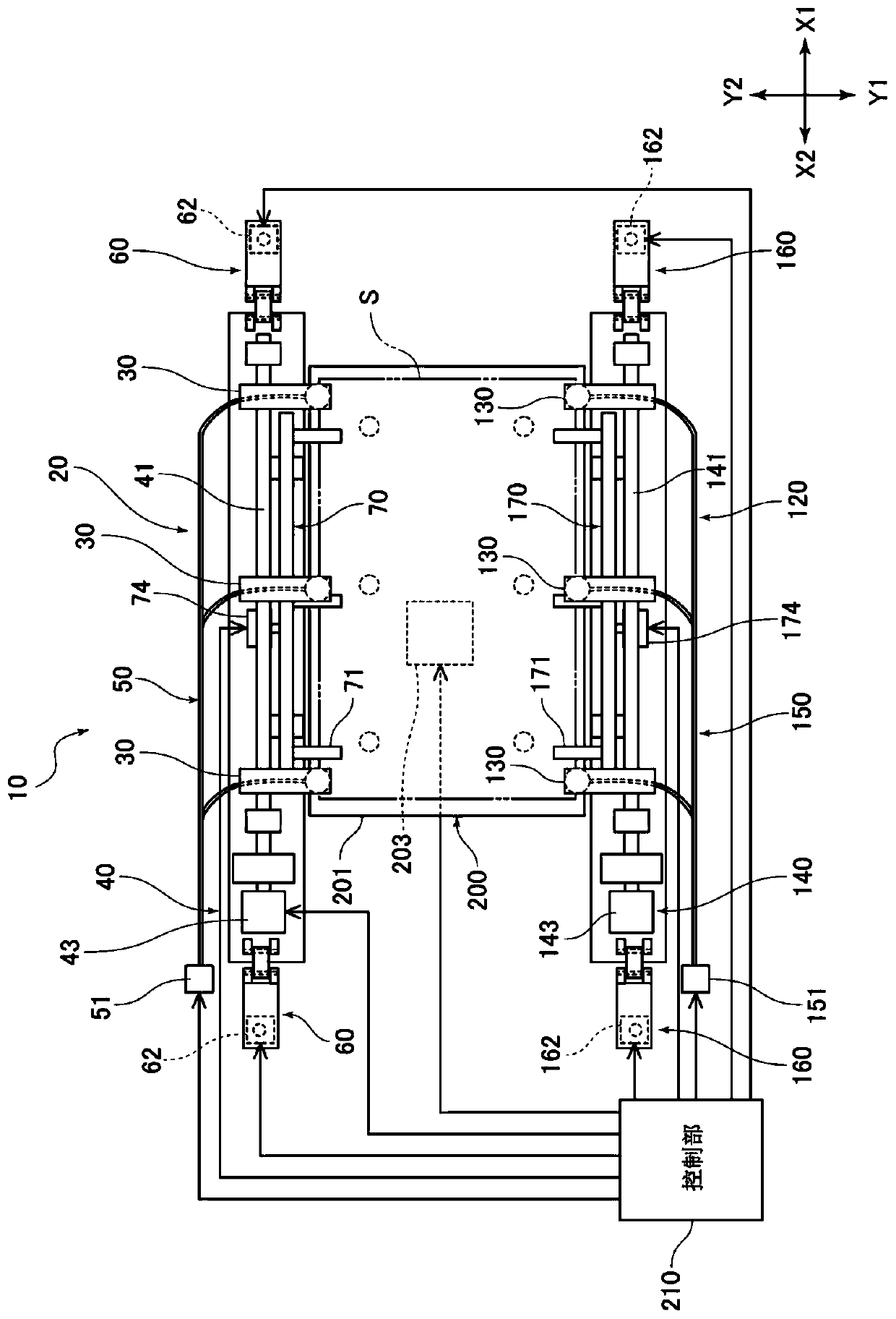
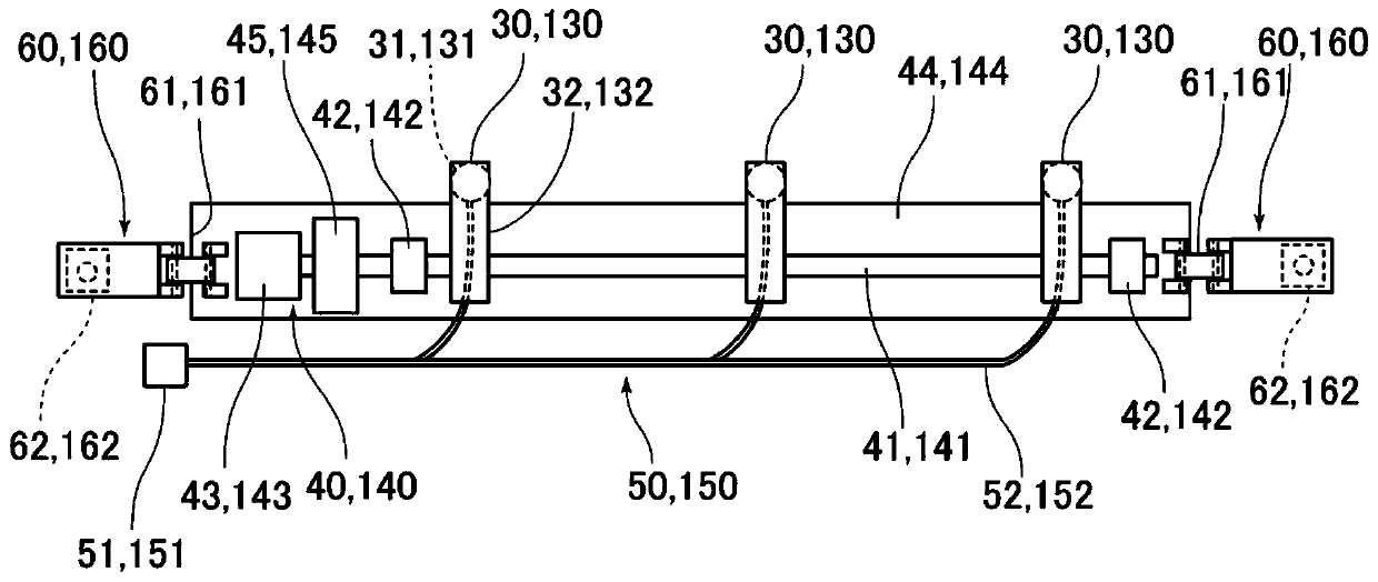
[0044] Hereinafter, the film take-out device 10 according to one embodiment of the present invention will be described. In the following description, the longitudinal direction of the support shaft 41 is referred to as the X direction, and the X1 side is figure 1 The right side of the paper in the X2 side is figure 1 on the left side of the paper. In addition, let the direction connecting the first adsorption unit 20 and the second adsorption unit 120 be the Y direction, and the Y1 side be figure 1 The front side of the paper in the Y2 side is figure 1 Backside of paper in . Additionally, connect Figure 5 The direction (up and down) of the suction base 220 and the stage unit 200 in the diagram is taken as the Z direction, and the Z1 side is Figure 5 The rear side (upper side) of the paper in , and the Z2 side is Figure 5 The front side (lower side) of the paper in the middle.

[0045] (About the configuration of the film take-out device)

[0046] figure 1 It is a s...


PUM


Abstract

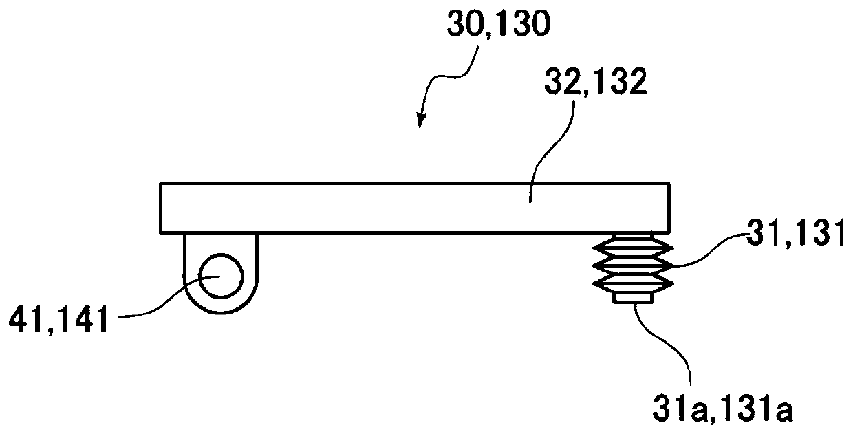
The invention provides a film withdrawing device and a manufacturing method of a flexible printed circuit board. The provided film withdrawing device can take out a plurality of film like members at the same time without generating any deformation on the film like members. The film withdrawing device (10) comprises a first attracting member (30) that can attract and hold one edge of a film like member (S); a second attracting member (130) that can attract and hold the other edge of the film like member (S); a first elevating member (60) that can lift or lower the first attracting member (30);a second elevating member (160) that can lift or lower the second attracting member (130); and a control part (210) that controls the movement of the first attracting member (30) and the second attracting member (130). The control part (210) controls the first attracting member (30) and the second attracting member (130) to attract and hold the uppermost film like member (S1) of a laminate (PS) and then makes any one of the first attracting member (30) and the second attracting member (130) go up or down relative to the other.

Description

technical field [0001] The present invention relates to a film take-out device and a method for manufacturing a flexible printed circuit board. Background technique [0002] In the manufacturing process of the flexible printed wiring board, there is a process of taking out one film-shaped member from a site where a plurality of film-shaped members such as copper foils are stacked, and providing it to another processing site. There is an apparatus disclosed in Patent Document 1 as an apparatus for taking out such a film-like member used in the manufacture of a flexible printed wiring board. In the structure disclosed in Patent Document 1, as a mechanism for preventing two film-like members from being taken out at the same time, it is specifically as follows: in a stacked state of a plurality of film-like members, the film at the end of the stacking order is sucked by a vacuum chuck. After the film-like part in the upper position, the first air cylinder is operated to raise t...

Claims


Application Information

Patent Timeline
Patent Type & Authority Applications(China)
IPC IPC(8): B65H3/08B65H3/46B65H3/50H05K3/00
CPCB65H3/0816B65H3/46B65H3/50H05K3/00B65H2701/173B65H2701/1131
Inventor 藤村隆之高木弘喜冈修平
Owner NIPPON MEKTRON LTD
Learn More