Supercharge Your Innovation With Domain-Expert AI Agents!

Terminal device control system and air conditioning unit

A terminal device and control system technology, which is applied in heating and ventilation control system, heating and ventilation safety system, control input related to air characteristics, etc., can solve the problem of easy imbalance in the adjustment of subordinate terminal devices, and achieve the effect of improving accuracy

Pending Publication Date: 2020-02-14
GREE ELECTRIC APPLIANCES INC
View PDF0 Cites 1 Cited by
  • Summary
  • Abstract
  • Description
  • Claims
  • Application Information

AI Technical Summary

Problems solved by technology

[0007] The present invention provides a terminal device control system and an air-conditioning unit to at least solve the problem in the prior art that there is a master-slave relationship among the common temperature controllers of multiple variable air volume terminal devices in a large space cabin, which leads to the problem that the adjustment of the slave terminal devices is easy to unbalance

Method used


Image

  • Terminal device control system and air conditioning unit
  • Terminal device control system and air conditioning unit
  • Terminal device control system and air conditioning unit

Examples


Embodiment 1

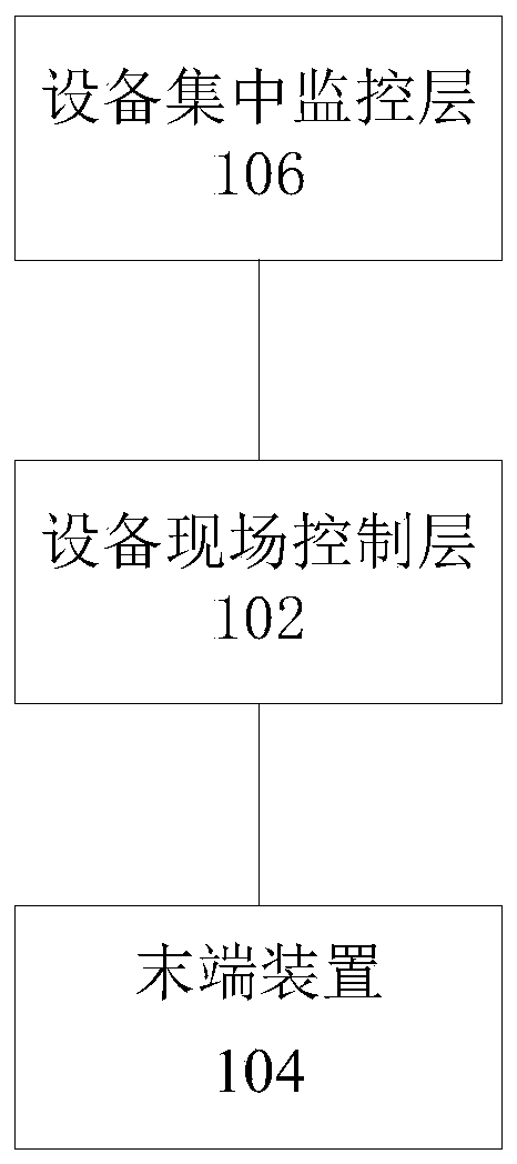
[0024] In the preferred embodiment 1 of the present invention, a terminal device control system is provided, which can be directly applied to various variable air volume terminal air conditioners, and can also be applied to other devices with terminal devices. Specifically, figure 1 shows an alternative structure diagram of the system, such as figure 1 As shown, the system includes:

[0025] The equipment field control layer 102 is connected with the terminal device 104 and is used for field control of the terminal device 104;

[0026] The equipment centralized monitoring layer 106 is connected with the equipment field control layer 102, and is used for overall monitoring of the terminal device 104 through the control equipment field control layer.

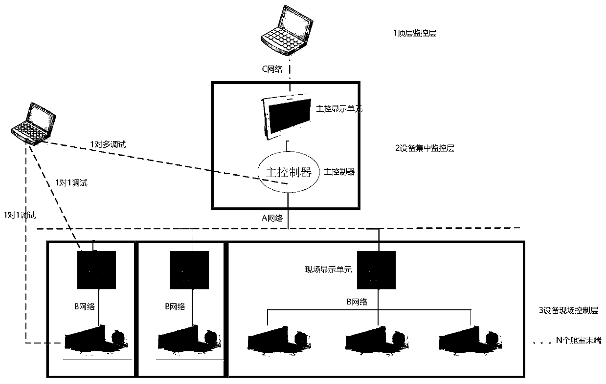
[0027] In the above embodiments, a variable air volume network architecture with multi-terminal devices distributed at the same level with common temperature controllers is proposed, including: an equipment on-site control layer...

Embodiment 2

[0040] Based on the terminal device control system provided in the above-mentioned embodiment 1, in preferred embodiment 2 of the present invention, an air conditioning unit is also provided, including the above-mentioned terminal device control system.

[0041] In the above embodiments, a variable air volume network architecture with multi-terminal devices distributed at the same level with common temperature controllers is proposed, including: an equipment on-site control layer connected to the end devices for on-site control of the end devices; an equipment centralized monitoring layer , which is connected to the equipment field control layer, and is used to monitor the terminal device as a whole through the control equipment field control layer. That is to say, the terminal devices share a set of temperature controllers-the equipment centralized monitoring layer, and the overall monitoring is carried out through the equipment centralized monitoring layer. At the same time, ...


PUM


Abstract

The invention discloses a terminal device control system and an air conditioning unit. The terminal device control system comprises an equipment field control layer and an equipment centralized monitoring layer, wherein the equipment field control layer is connected with a terminal device and used for conducting field control over the terminal device; and the equipment centralized monitoring layeris connected with the equipment field control layer and used for conducting overall monitoring on the terminal device by controlling the equipment field control layer. By means of the terminal devicecontrol system and the air conditioning unit, the problem that in the prior art, a master-slave relation exists between a plurality of variable-air-volume terminal device common temperature controllers of a large space cabin, and consequently adjustment of a slave terminal device is prone to being unbalanced is solved, and the air conditioning control precision of the multi-terminal common temperature controllers, the adaptability to the use environment and the control system debugging convenience are improved.

Description

technical field [0001] The present invention relates to the technical field of air conditioning, in particular to a terminal device control system and an air conditioning unit. Background technique [0002] With the development of air-conditioning technology in recent years, variable air volume technology is emerging and gradually becoming a respected all-air air-conditioning system due to its remarkable comfort and energy-saving properties. The core of the variable air volume air conditioning system lies in the control system. The variable air volume control systems of various manufacturers in the industry mainly follow the standard building communication protocols, such as Modbus / Bacnet / CAN. The operation effect, system debugging and maintenance convenience play a far-reaching role. [0003] For the design and application of VAV terminal devices in large-space cabins, the existing VAV system adopts the following conventional methods: [0004] Configure multiple small air...

Claims


Application Information

Patent Timeline
IPC IPC(8): F24F11/30F24F11/52F24F11/58F24F11/64F24F11/74F24F11/80F24F11/88F24F110/10
CPCF24F11/30F24F11/52F24F11/58F24F11/64F24F11/74F24F11/80F24F11/88F24F2110/10
Inventor 张龙爱李志海王严杰迟亚玲孙宝茹尹永存范学瑞袁佳旭
Owner GREE ELECTRIC APPLIANCES INC
Features
  • R&D
  • Intellectual Property
  • Life Sciences
  • Materials
  • Tech Scout
  • Unparalleled Data Quality
  • Higher Quality Content
  • 60% Fewer Hallucinations
Learn More