High-pressure gas desorption visbreaking rotary tillage cutter, rotary tiller and rotary tillage method of rotary tiller

A technology of high-pressure gas and rotary tiller, which is applied in the fields of tillage implements, agricultural machinery and implements, etc. It can solve the problems of increased cutter resistance and reduced cutter life, so as to reduce friction, reduce tillage resistance and increase service life. Effect

Active Publication Date: 2020-02-18
SOUTH CHINA AGRI UNIV
View PDF11 Cites 1 Cited by
  • Summary
  • Abstract
  • Description
  • Claims
  • Application Information

AI Technical Summary

Problems solved by technology

[0002] At present, the commonly used rotary tillage cutter is in direct contact with the soil, relying on the high-speed rotating centrifugal force of the cutter to throw the soil away from the cutter, but the soil is relatively viscous and adheres to the surface of the tillage cutter, which increases the resistance of the cutter during tillage and reduces the life of the cutter.

Method used


Image

  • High-pressure gas desorption visbreaking rotary tillage cutter, rotary tiller and rotary tillage method of rotary tiller
  • High-pressure gas desorption visbreaking rotary tillage cutter, rotary tiller and rotary tillage method of rotary tiller
  • High-pressure gas desorption visbreaking rotary tillage cutter, rotary tiller and rotary tillage method of rotary tiller

Examples


Embodiment 1

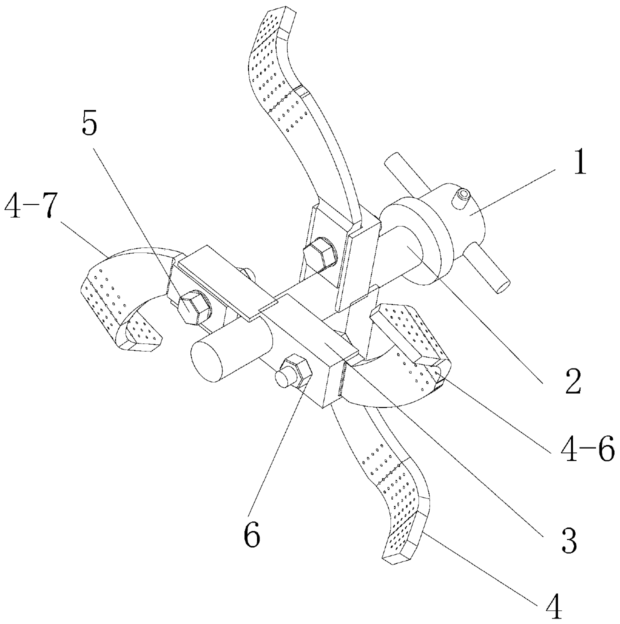
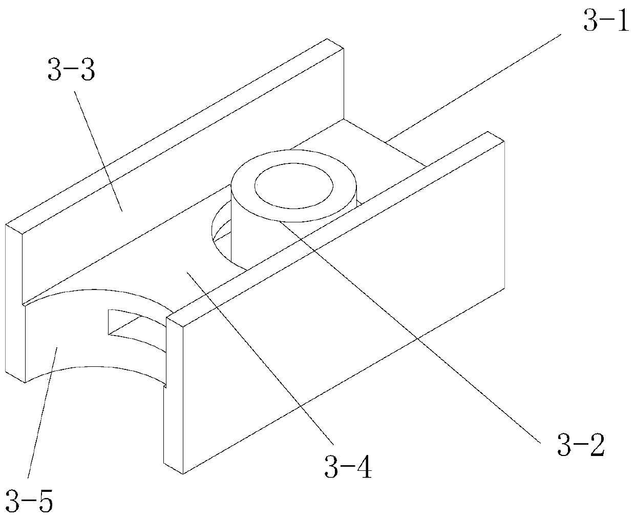
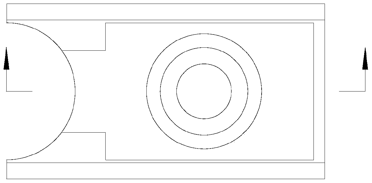
[0047] A high-pressure gas desorption and viscosity-reducing rotary tillage cutter head includes a pneumatic slip ring, a hollow cutter shaft, a cavity cutter holder, a hollow cutter, shoulder screws and nuts. The hollow knife shaft is connected to the machine frame in a rotating manner, and a pneumatic slip ring is installed between the hollow knife shaft and the machine frame. on the frame; the pneumatic slip ring, hollow cutter shaft, cavity tool holder, and hollow tool are all equipped with cavities, and the cavities of the pneumatic slip ring, hollow cutter shaft, cavity tool holder, and hollow tool are connected in sequence; on the pneumatic slip ring There is a trachea interface; the soil-contacting part of the hollow cutter is provided with multiple evenly distributed air outlets.

[0048] The pneumatic slip ring includes a stator part and a rotor part, the cavities of the stator part and the rotor part communicate with each other, and the rotor part rotates relative t...

Embodiment 2

[0056] A rotary tiller, comprising a gas source and a high-pressure gas desorption and viscosity-reducing rotary tiller disc of Embodiment 1; the gas source providing high-pressure gas is connected to the gas pipe interface of the pneumatic slip ring through a gas pipe.

[0057] A rotary tillage method of a rotary tiller, using a rotary tiller, high-pressure gas is ejected through the air outlet of the hollow cutter to blow the soil away, and at the same time, with the high-speed rotation of the rotary tiller, the high-pressure gas flows between the hollow cutter and the rotary tiller. An air film that reduces soil adhesion is formed between the soils, reducing soil adhesion.

[0058] The parts not mentioned in this embodiment are the same as those in Embodiment 1.


PUM


Abstract

The invention relates to a high-pressure gas desorption visbreaking rotary tillage cutter which comprises a pneumatic sliding ring, a hollow tool shaft, a cavity tool rest and a hollow tool. The hollow tool shaft is rotatably connected with a machine frame, the pneumatic sliding ring is mounted between the hollow tool shaft and the machine frame, the cavity tool rest is mounted on the hollow toolshaft, the hollow tool is mounted on the cavity tool rest, cavities are formed in the pneumatic sliding ring, the hollow tool shaft, the cavity tool rest and the hollow tool, the cavities of the pneumatic sliding ring, the hollow tool shaft, the cavity tool rest and the hollow tool are sequentially communicated, a gas pipe joint is arranged on the pneumatic sliding ring, and a plurality of uniformly distributed gas outlet holes are formed in a soil-engaging component of the hollow tool. The invention further relates to a rotary tiller and a rotary tillage method thereof, and belongs to the technical field of agricultural equipment. High-pressure gas is blown out from the gas outlet holes of the hollow tool, soil is directly blown away, and adhesion is decreased. Along with high-speed rotation of the rotary tillage cutter, the high-pressure gas forms an air isolation film between the rotary tillage cutter and the soil, and soil adhesion is decreased.

Description

technical field [0001] The invention relates to the technical field of agricultural machinery and tools, in particular to a high-pressure gas desorption and viscosity-reducing rotary tillage cutter head, and also relates to a rotary tiller using the rotary tiller cutter head and a rotary tillage method thereof. Background technique [0002] At present, the commonly used rotary tillage cutter directly contacts the soil, relying on the high-speed rotating centrifugal force of the cutter to throw the soil away from the cutter. However, the soil is highly viscous and adheres to the surface of the tillage cutter, which increases the resistance of the cutter during tillage and reduces the life of the cutter. [0003] The applicant found that if the third factor—high-pressure gas is introduced between the cutter and the soil, an air film is formed between the cutter and the soil, which will greatly reduce the adhesion of the soil to the cutter, reduce the tillage resistance, and imp...

Claims


Application Information

Patent Timeline
Patent Type & Authority Applications(China)
IPC IPC(8): A01B33/10
CPCA01B33/10
Inventor 杨洲孙志全段洁利谢恒李君金鸿
Owner SOUTH CHINA AGRI UNIV
Why Eureka
Try Eureka