Automatic punching and bending device for filter element end covers

A stamping bending and end cap technology, applied in the field of stamping, can solve the problems of affecting the processing speed, affecting the processing accuracy of the filter element end cap, single function, etc., and achieve the effect of a stable stamping process

Pending Publication Date: 2020-02-18
江苏宏仕达环保科技有限公司
View PDF0 Cites 3 Cited by
  • Summary
  • Abstract
  • Description
  • Claims
  • Application Information

AI Technical Summary

Problems solved by technology

[0003] The end cap of the filter element often contains multiple structures such as holes, bends, and protrusions. At present, most of the processing equipment used for the end cap of the filter element has a single function, and multiple processing equipment such as punching machines, bending machines, and punching machines are required to complete the processing process. , that is, after the stamping of one structure is completed, the filter element end cover is transferred to the next production link, and another processing equipment completes the processing of the next structure, resulting in low processing efficiency of the filter element end cover, between each processing equipment When switching, it is necessary to reposition the end cover of the filter element to be punched, which not only affects the processing speed, but also easily causes processing errors and affects the processing accuracy of the end cover of the filter element

Method used


Image

  • Automatic punching and bending device for filter element end covers
  • Automatic punching and bending device for filter element end covers
  • Automatic punching and bending device for filter element end covers

Examples


Embodiment Construction

[0021] The preferred embodiments of the present invention will be described in detail below in conjunction with the accompanying drawings, so that the advantages and features of the present invention can be more easily understood by those skilled in the art, so as to define the protection scope of the present invention more clearly.

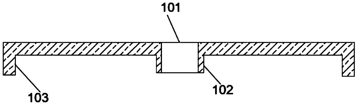
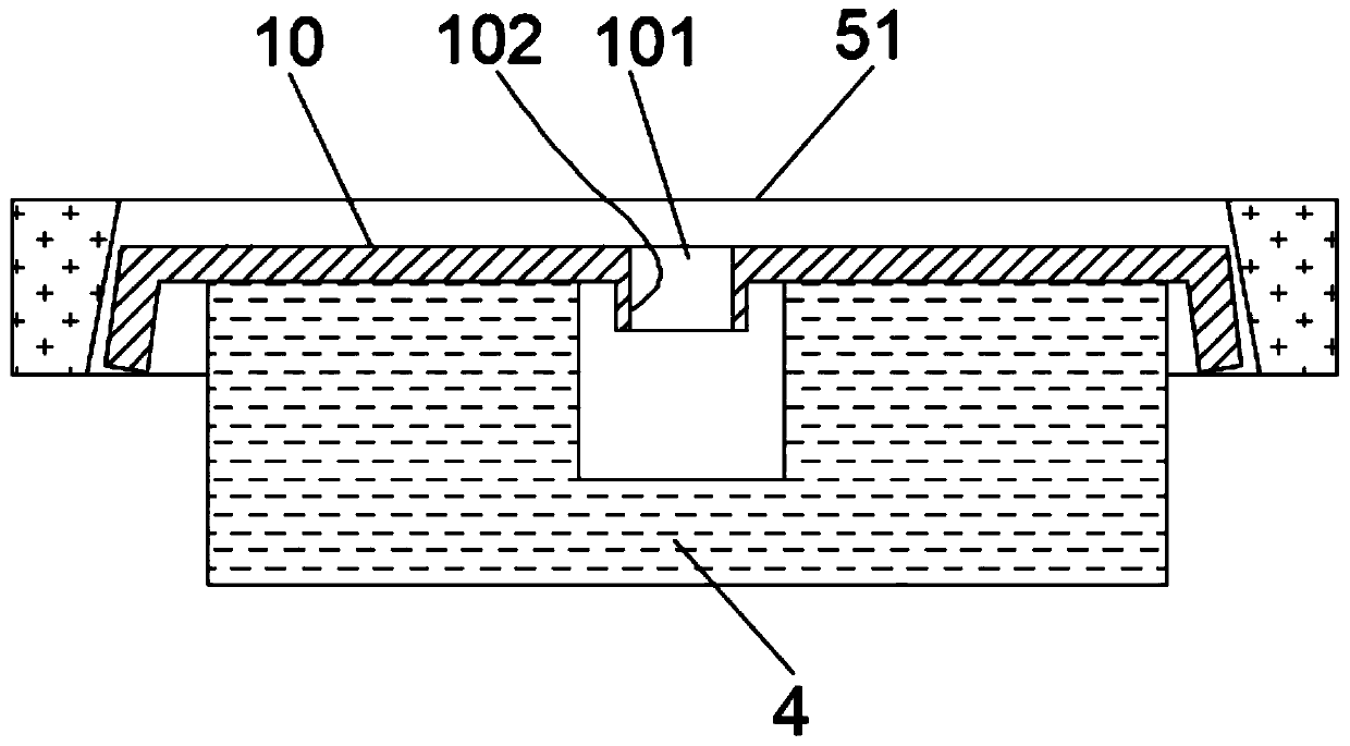
[0022] The automatic stamping and bending device of the filter element end cover of the present invention is suitable for figure 1 In the stamping of the shown end cap, a through central hole 101 is provided in the middle of the filter element end cap, a flange 102 extending downward is provided around the central hole 101, and an edge portion 103 of the filter element end cap extends downward.

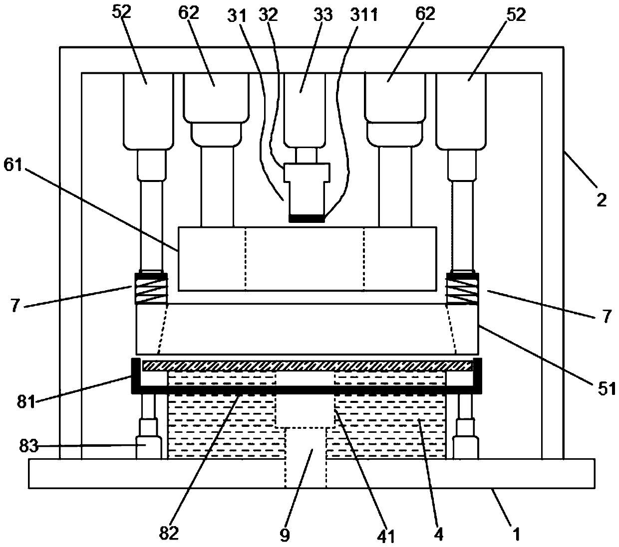
[0023] see figure 2 As shown, the automatic punching and bending device for the filter element end cover of the present invention includes a workbench 1 and a gantry 2 connected to the workbench 1 and arranged above it, a first stamping module, a lower ...


PUM


Abstract

The invention discloses an automatic punching and bending device for filter element end covers. The automatic punching and bending device comprises a workbench, a portal frame, a first punching module, a lower forming part, a second punching module and a pressing part, wherein the portal frame, the first punching module, the lower forming part, the second punching module and the pressing part areconnected with the workbench; the lower forming part is fixed to the workbench, and a punching groove is formed in the middle of the lower forming part; the pressing part is positioned above the groove wall of the punching groove; the first punching module comprises a first punching head, a forming boss and a first air cylinder, the first punching head is arranged at the lower end of the first punching module, the first air cylinder is fixed to the portal frame, and an annular cutter is arranged at the end, close to a sheet material to be punched, of the punching head; and the second punchingmodule comprises a second punching head and air cylinders driving the second punching head to move downwards, and the second punching head can move to the outer side of the lower forming part and thenare clamped with the lower forming part. According to the automatic punching and bending device, multiple processes of piecing, bending, punching and the like of the filter element end covers are carried out intensively on the device, so that a processing device does not need to be replaced in the processing process of the filter element end covers, and then the processing efficiency is effectively improved.

Description

technical field [0001] The invention relates to the field of stamping technology, in particular to an automatic stamping and bending device for a filter element end cover. Background technique [0002] Car filter is an important part of car engine, car filter mainly includes fuel filter, air filter and oil filter. The key component of the filter is the filter element, through which the substance to be filtered (such as fuel, engine oil, air, etc.) passes through the filter element to achieve its filtering effect. The filter element is made of materials with adsorption or filtering functions, and it is a hollow tubular structure. Therefore, the installation and use of the filter element cannot be separated from the filter element end caps placed at both ends of the filter element. [0003] The end cap of the filter element often contains multiple structures such as holes, bends, and protrusions. At present, most of the processing equipment used for the end cap of the filter ...

Claims


Application Information

Patent Timeline
Patent Type & Authority Applications(China)
IPC IPC(8): B21D35/00B21D28/26B21D28/04B21D5/01B21D43/00B21D22/02
CPCB21D5/002B21D5/01B21D22/02B21D28/04B21D28/26B21D35/001B21D35/002B21D43/003
Inventor 薛涛
Owner 江苏宏仕达环保科技有限公司
Why Eureka
Try Eureka