Stamping mechanism for automobile door lock catch production line

A technology of automobile door locks and stamping mechanisms, which is applied in the field of stamping mechanisms, can solve problems such as low production efficiency, high cost, and complicated production processes of ordinary locks, and achieve the effects of high production efficiency, compact structure, and low product scrap rate

Active Publication Date: 2016-07-06
蚌埠安知知识产权运营有限公司
View PDF5 Cites 1 Cited by
  • Summary
  • Abstract
  • Description
  • Claims
  • Application Information

AI Technical Summary

Problems solved by technology

[0002] With the development of the economy, automobiles have become a means of transportation for people to use daily. Automobile door locks mainly include lock body, lock catch and driving mechanism. The lock body is the main part of the door lock and is generally installed on the car door. The matching part of the lock body is usually installed on the car body corresponding to the lock body. The driving mechanism refers to the transmission member of actions and forces such as key unlocking and handle unlocking. The lock catch is essential to complete the closing function of the car door lock. The buckle production process is more complicated, the production efficiency is low, and the cost is high

Method used


Image

  • Stamping mechanism for automobile door lock catch production line
  • Stamping mechanism for automobile door lock catch production line
  • Stamping mechanism for automobile door lock catch production line

Examples


Embodiment Construction

[0011] The preferred embodiments of the present invention will be described in detail below in conjunction with the accompanying drawings, so that the advantages and features of the invention can be more easily understood by those skilled in the art, so as to define the protection scope of the present invention more clearly.

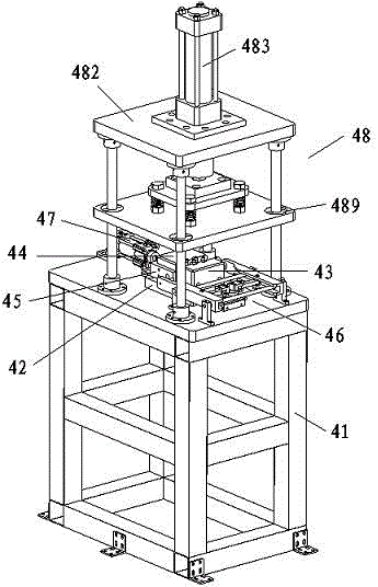
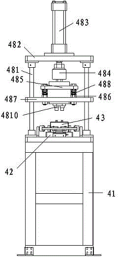
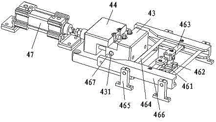
[0012] see Figure 1 to Figure 3 , the embodiment of the present invention includes:

[0013] A stamping mechanism of an automobile door lock production line, the stamping mechanism of the automobile door lock production line includes a stamping machine base 41, a backing plate 42, a stamping fixed die 43, a stamping guide die 44, a guide limit plate 45, and a clamping and positioning assembly 46. ​​Stamping push-pull cylinder 47 and stamping assembly 48, a backing plate 42 is installed on the flat plate of the stamping machine base 41, a stamping fixed die 43 and a stamping guide die 44 are installed on the backing plate 42, and the stamping fixed die 4...


PUM


Abstract

The invention discloses a stamping mechanism for an automobile door lock catch production line. The stamping mechanism for the automobile door lock catch production line comprises a stamping machine base, a base plate, a stamping and fixing die, a stamping and guiding die, a guiding and limiting plate, a clamping and locating assembly, a stamping push-pull air cylinder and a stamping assembly. The base plate is mounted on an upper flat plate on the stamping machine base. The stamping and fixing die and the stamping and guiding die are mounted on the base plate. The lower portions of the opposite inner side faces of the stamping and fixing die and the stamping and guiding die are connected through a pin bolt in a located manner. Limiting holes are formed in the two ends of the stamping and fixing die. The clamping and locating assembly is arranged at the front end of the stamping and fixing die. The stamping push-pull air cylinder is mounted on the position, at the rear end of the stamping and guiding die, of the upper flat plate of the stamping machine base. A piston rod of the stamping push-pull air cylinder is fixedly connected with the stamping and guiding die. The stamping assembly is arranged above the stamping and fixing die and the stamping and guiding die. By means of the manner, the stamping mechanism is compact in structure, stable in stamping, low in product rejection rate and high in production efficiency.

Description

technical field [0001] The invention relates to the field of mechanical automation, in particular to a stamping mechanism for an automobile door lock production line. Background technique [0002] With the development of the economy, automobiles have become a means of transportation for people to use daily. Automobile door locks mainly include lock body, lock catch and driving mechanism. The lock body is the main part of the door lock and is generally installed on the car door. The matching part of the lock body is usually installed on the car body corresponding to the lock body. The driving mechanism refers to the transmission member of actions and forces such as key unlocking and handle unlocking. The lock catch is essential to complete the closing function of the car door lock. The buckle manufacturing process is more complicated, the production efficiency is low, and the cost is high. Contents of the invention [0003] The technical problem mainly solved by the invent...

Claims


Application Information

Patent Timeline
IPC IPC(8): B21D22/02B21D37/10B21D53/38
CPCB21D22/02B21D37/10B21D53/38
Inventor 李红博
Owner 蚌埠安知知识产权运营有限公司
Why Eureka
Try Eureka