
Planar-type punching machine with five-guide-rod structure

A technology of gantry and guide rods, which is applied in the direction of presses and manufacturing tools, can solve the problems of uneven force on sliders and molds, affecting the quality of stamping products, and uneven force, so as to overcome instability and deformation of equipment parts Problems, reasonable structural design, and stable stamping process

Active Publication Date: 2013-05-08
广东虹瑞智能设备股份有限公司
View PDF8 Cites 1 Cited by
  • Summary
  • Abstract
  • Description
  • Claims
  • Application Information

AI Technical Summary

Problems solved by technology

However, the existing gantry punch press is only connected to the slider by a steel pipe in structure. During stamping production, since there is no guide point for the stress point around the slider, it is easy to cause stress on the left and right sides or front and rear sides of the slider and the mold. The uneven force makes the precision products receive uneven force during stamping and forming, and the unstable result will inevitably seriously affect the quality of stamping products

Method used


Image

  • Planar-type punching machine with five-guide-rod structure
  • Planar-type punching machine with five-guide-rod structure
  • Planar-type punching machine with five-guide-rod structure

Examples


Embodiment Construction

[0014] The present invention will be described in detail below in conjunction with the accompanying drawings and specific embodiments, but it is not intended to limit the present invention.

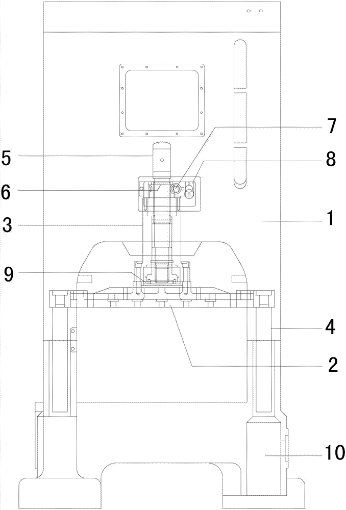
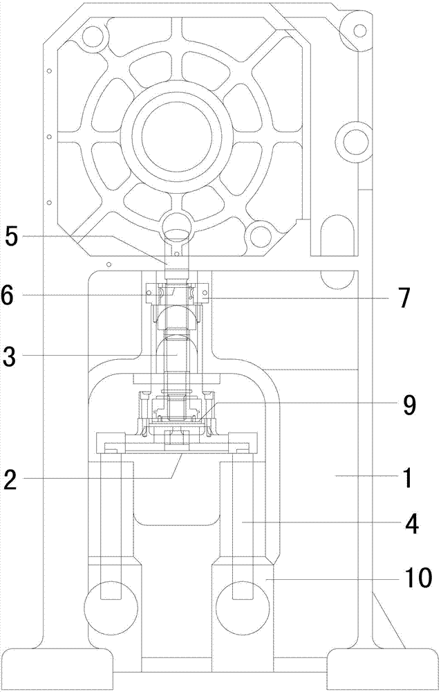
[0015] combine figure 1 , figure 2 As shown, the bed 1 of the present invention is equipped with a slide block 2 thereon, and a steel pipe 3 is fixed above the slide block 2 at the center position above it. The steel pipe 3 is embedded with a piston 9 at the junction with the slide block 2. An adjustment screw 5 is installed above it, and a transmission device composed of a worm gear 6 and a worm 7 meshing with each other is also provided between the steel pipe 3 and the adjustment screw 5, and the transmission device is installed on the steel pipe 3 through a worm gear fixing seat 8. superior.

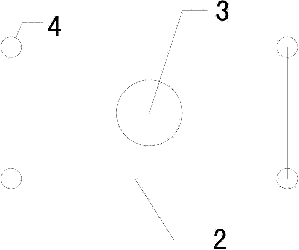
[0016] The bottom of the slider 2 holds a guide post 4 at the corners of the four sides, and the bottom end of each guide post is respectively sleeved in the corresponding guide sleeve 10, so ...


PUM


Abstract

The invention provides a planar-type punching machine with a five-guide-rod structure. The five-guide-rod structure is composed of a lathe bed with a sliding block. A steel pipe is arranged above the sliding block. An adjusting screw and a transmission device are installed above the steel pipe. Guide posts are arranged below the sliding block in an abutted mode. The guide posts are respectively support four corners of the sliding block in an abutted mode. The steel pipe, the guide posts and the sliding block are of integrated structures. The guide posts and the steel pipe are arranged at the top and the bottom of the sliding block to form a five-guide-rod structure. When the planar-type punching machine works, a stress punching point is located in the middle of the sliding block, guidance quality with a same force around the sliding block is obtained, and therefore the stress point of the sliding block is enabled to be stable, and the stress of stamping products is enabled to be uniform and stable. The problem that a stress point of the exiting annular guide post on a steel pipe is not uniform and stable is solved. Progressive contributions on the stamping industry are made.

Description

Technical field: [0001] The invention relates to the field of machine tool processing equipment, and specifically refers to a punching machine which adopts an integrated structure and can improve the force uniformity and stability of a punched plate. Background technique: [0002] The main function of the stamping machine is the stamping of the mold, and the gantry punch is the most widely used machine tool, and the stability of its structure has a huge impact on the stamping effect and quality of various plates. However, the structure of the existing gantry punch presses is only connected to the slider by a steel pipe. During stamping production, since the stress points around the slider have no guide points, it is easy to cause stress on the left and right sides or front and rear sides of the slider and the mold. The uneven force makes the precision products receive uneven force during stamping and forming, and the unstable result will inevitably seriously affect the quali...

Claims


Application Information

Patent Timeline
Patent Type & Authority Applications(China)
IPC IPC(8): B30B15/04
Inventor 龚建锋
Owner 广东虹瑞智能设备股份有限公司
Learn More