U-shaped bending machine for building

A technology for bending machines and construction, applied in the field of bending machines, can solve the problems that steel bars are not practical, difficult to realize, and difficult to bend technology, so as to avoid excessive or insufficient bending, and to achieve good bending effect. simple structure

Inactive Publication Date: 2020-02-18
湖南天河建设工程有限公司
View PDF4 Cites 4 Cited by
  • Summary
  • Abstract
  • Description
  • Claims
  • Application Information

AI Technical Summary

Problems solved by technology

[0005] Aiming at the deficiencies of the existing technology, the present invention provides a U-shaped bending machine for construction, which solves the problem that the existing bending technology is not practical for some steel bars with requirements or continuous multiple bending, especially for some steel hoops. The four corners are bent into a U-shape. This kind of bending technology is difficult and difficult to realize.

Method used


Image

  • U-shaped bending machine for building
  • U-shaped bending machine for building
  • U-shaped bending machine for building

Examples


Embodiment 1

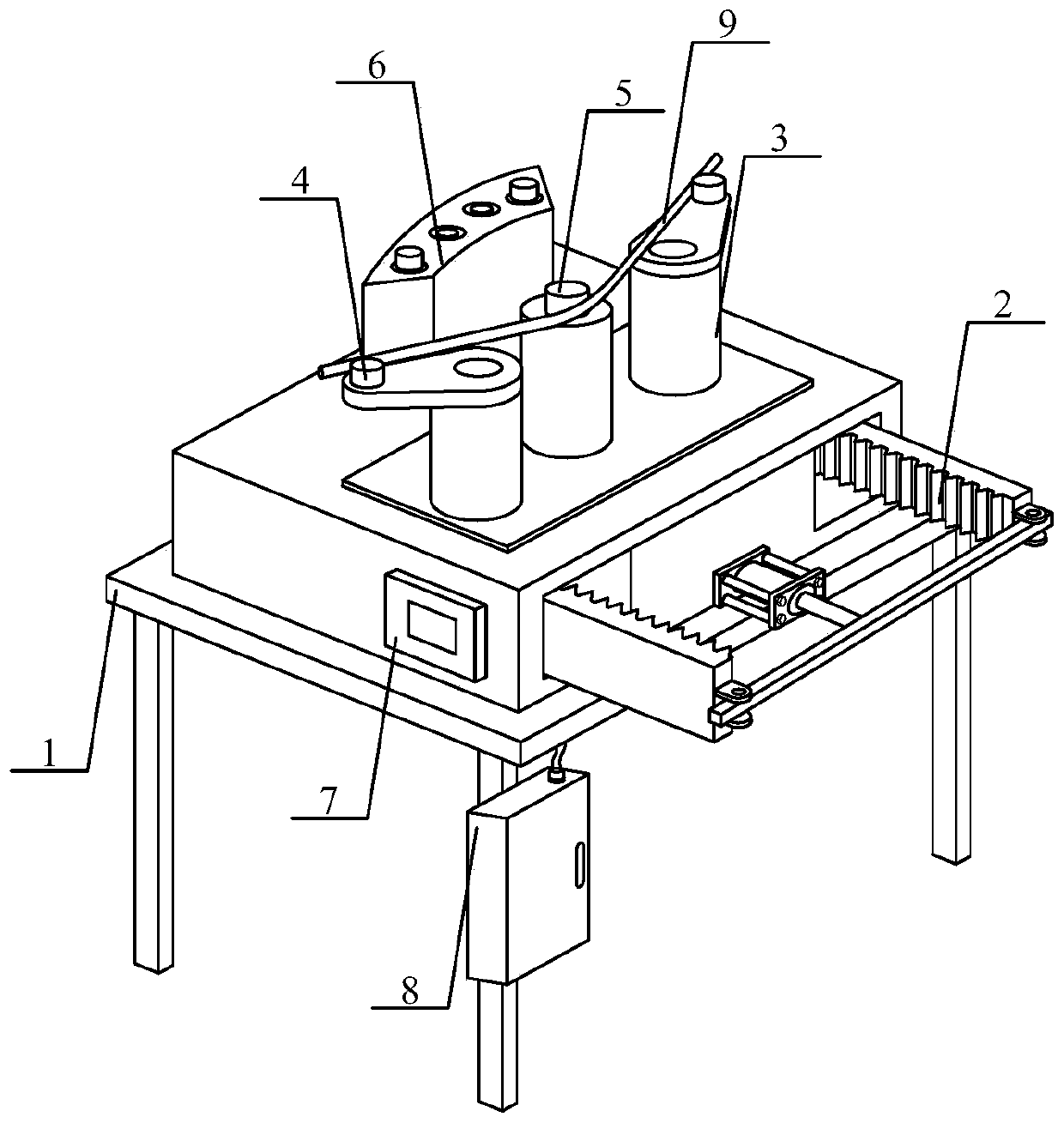
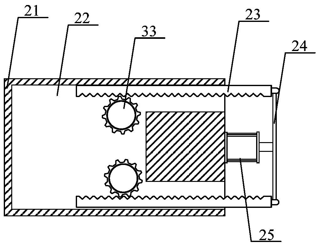
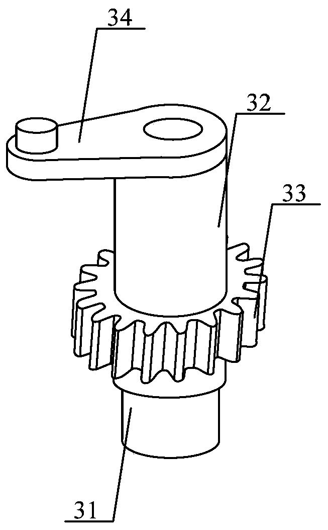
[0027] Such as Figure 1-6 As shown, the present invention provides a technical solution: a U-shaped bending machine for construction, including a frame body, a driving mechanism, a first bending mechanism, a second bending mechanism, a fixing piece, a limit mechanism, and a push cylinder Controller, junction box and steel bars, the frame body is welded by 4 angle irons and a rectangular steel plate, and the angle irons are welded at the four corners of the bottom of the rectangular steel plate; the drive mechanism is installed on the frame body through bolts above; the first bending mechanism and the second bending mechanism are arranged on the driving mechanism, and are detachably connected with the driving mechanism; the fixing member is arranged between the first bending mechanism and the second bending mechanism The fixing part is vertically welded at the middle position of the top of the driving mechanism; the limit mechanism is arranged on the left side of the fixing pa...

Embodiment 2

[0029] A U-shaped bending machine for construction, including a frame body, a driving mechanism, a first bending mechanism, a second bending mechanism, a fixing piece, a limit mechanism, a push cylinder controller, a junction box and a steel bar, the described The frame body is welded by 4 angle irons and a rectangular steel plate, and the angle irons are welded at the four corners of the bottom of the rectangular steel plate; the driving mechanism is installed on the frame body through bolts; the first bending mechanism and The second bending mechanism is arranged on the driving mechanism and is detachably connected with the driving mechanism; the fixing piece is arranged between the first bending mechanism and the second bending mechanism, and the fixing piece is vertically welded on the top of the driving mechanism The middle position; the limit mechanism is arranged on the left side of the fixing part, and the limit mechanism is welded with the top of the fixing part; the p...

Embodiment 3

[0032]A U-shaped bending machine for construction, including a frame body, a driving mechanism, a first bending mechanism, a second bending mechanism, a fixing piece, a limit mechanism, a push cylinder controller, a junction box and a steel bar, the described The frame body is welded by 4 angle irons and a rectangular steel plate, and the angle irons are welded at the four corners of the bottom of the rectangular steel plate; the driving mechanism is installed on the frame body through bolts; the first bending mechanism and The second bending mechanism is arranged on the driving mechanism and is detachably connected with the driving mechanism; the fixing piece is arranged between the first bending mechanism and the second bending mechanism, and the fixing piece is vertically welded on the top of the driving mechanism The middle position; the limit mechanism is arranged on the left side of the fixing part, and the limit mechanism is welded with the top of the fixing part; the pu...


PUM


Abstract

The invention discloses a U-shaped bending machine for a building. The U-shaped bending machine comprises a rack body, a driving mechanism, a first bending mechanism, a second bending mechanism, a fixing piece, a limiting mechanism, a push cylinder controller, a junction box and a steel bar. According to the U-shaped bending machine, the driving mechanism is arranged, a rack drives the first bending mechanism and the second bending mechanism to act through a gear, the synchronism is high, the bent arc shape is uniform, and the U-shaped bending machine is suitable for bending steel bar pieces with high bending precision; the first bending mechanism and the second bending mechanism are arranged, the structure is simple, the bending effect is good, and the labor intensity is low; the fixing piece is arranged, a bending column is arranged to be in a girdling shape, the situation that the steel bar or a steel pipe slips off or collapses out during bending can be prevented, and the safety ofthe machine is guaranteed; and the limiting mechanism is arranged, the steel bars with different bending degrees are subjected to bending limiting length adjustment by adjusting limiting columns in acontaining groove, and the situation that bending is excessive or insufficient is avoided.

Description

technical field [0001] The invention relates to the technical field of bending machines, in particular to a U-shaped bending machine for construction. Background technique [0002] In the process of building construction, in order to make the building more stable, it is necessary to use steel bars, and in order to better use the steel bars, it is necessary to bend a part of the steel bars. Now, construction workers usually press the steel bar with one hand, and then press it with the other hand. Steel bars, to bend the steel bars, so it is difficult to control the bending angle of the steel bars, and the construction workers are tired, so the construction workers will clamp the steel bars on the vise, after the steel bars are bent, and then operate the vise to bend the bent The steel bars are loose, which is more troublesome. [0003] The existing bending technology is not practical for some steel bars that require continuous bending or multiple bending. In particular, some...

Claims


Application Information

Patent Timeline
Patent Type & Authority Applications(China)
IPC IPC(8): B21F1/00
CPCB21F1/00
Inventor 王磊王彩云
Owner 湖南天河建设工程有限公司
Why Eureka
Try Eureka