Crown block slide wire collector

A sliding line set, crane technology, applied in the directions of transportation and packaging, load hanging components, etc., can solve the problems of easy jumping, reduction of sliding vane height, ignition, etc., to avoid inconsistent wear, ensure normal operation, increase The effect of roundness

Inactive Publication Date: 2020-02-18
HENGYANG RAMON SCI & TECH CO LTD
View PDF0 Cites 0 Cited by
  • Summary
  • Abstract
  • Description
  • Claims
  • Application Information

AI Technical Summary

Problems solved by technology

[0005] Aiming at the deficiencies of the prior art, the present invention provides a trolley wire collector for a crane, which solves the problem that the existing trolley wire collector tends to jump when it runs to the position where the two trolley wires touch, which leads to sparking. Occurrence, after excessive wear of the sliding plate, the height of the sliding plate in the sliding line is reduced, and the sliding line collector is prone to fall out of the sliding line, thus affecting the normal operation of the crane and the crane

Method used


Image

  • Crown block slide wire collector
  • Crown block slide wire collector
  • Crown block slide wire collector

Examples


Embodiment 1

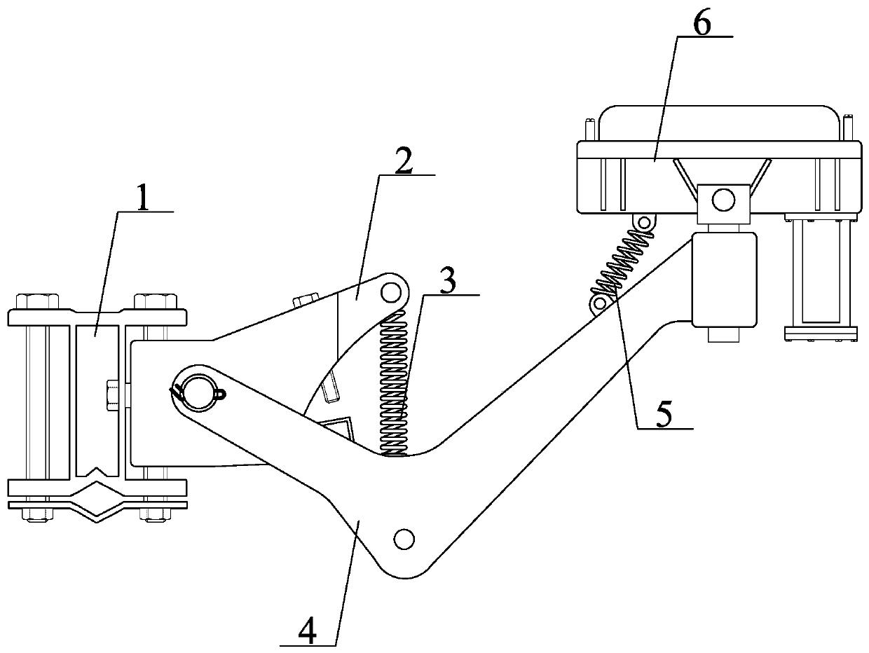
[0027] Such as Figure 1-5 As shown, the present invention provides a technical solution: a sliding wire collector for a crane, including a crane end mounting frame, a swing arm mechanism, a tension spring, a support arm mechanism, an anti-drop spring and a current collector, the The swing arm mechanism is movably connected with the mounting frame at the end of the crane; the two ends of the tension spring are respectively buckled on the first pin shaft and the second pin shaft; the support arm mechanism is connected with the swing arm mechanism through the rotating shaft , the support arm mechanism is connected to the current collector through the anti-off spring; the current collector is plugged into the right end of the support arm mechanism.

Embodiment 2

[0029] A sliding wire collector for a crane, including a crane end mounting frame, a swing arm mechanism, a tension spring, a support arm mechanism, an anti-drop spring and a current collector, and the swing arm mechanism is movable with the crane end mounting frame connection; the two ends of the tension spring are buckled respectively on the first pin shaft and the second pin shaft; The electric device is connected; the current collecting device is plugged into the right end of the support arm mechanism.

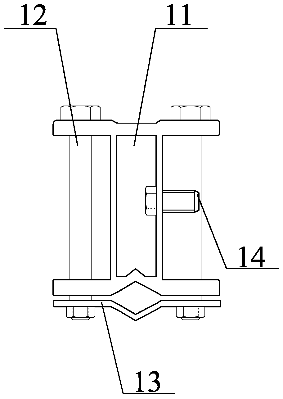
[0030] Preferably, the mounting frame at the end of the crane includes a fixing frame, bolts, cards and fixing bolts, the fixing frame is set in the shape of "I", and bolt holes are opened at the four corners; two bolts are used, Through the fixing frame and the card are fixed by nuts; the middle position of the card in contact with the fixing frame is diamond-shaped; the fixing bolt is threaded with the fixing frame, the bolt passes through the fixing frame and the connec...

Embodiment 3

[0032] A sliding wire collector for a crane, including a crane end mounting frame, a swing arm mechanism, a tension spring, a support arm mechanism, an anti-drop spring and a current collector, and the swing arm mechanism is movable with the crane end mounting frame connection; the two ends of the tension spring are buckled respectively on the first pin shaft and the second pin shaft; The electric device is connected; the current collecting device is plugged into the right end of the support arm mechanism.

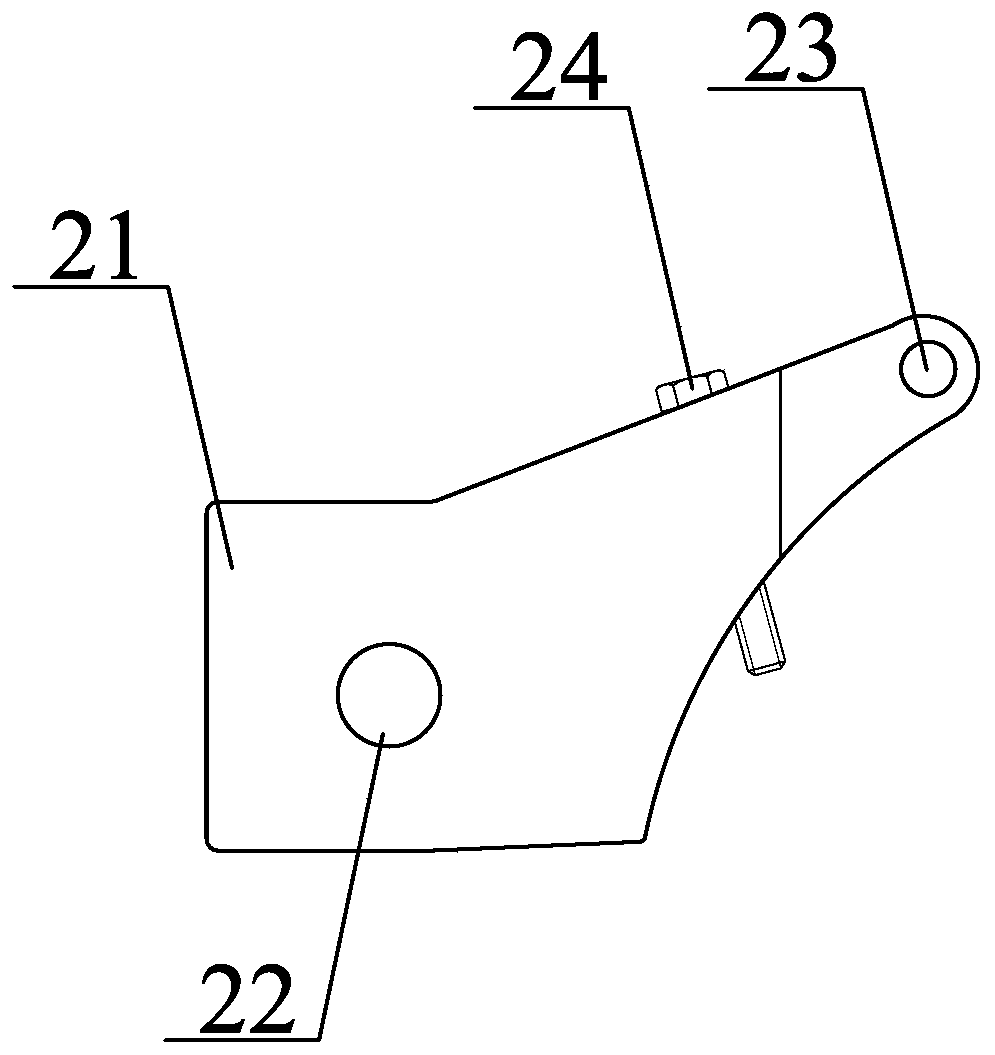
[0033] Preferably, the swing arm mechanism includes a boom, a shaft hole, a first pin shaft and a limit bolt, and the boom is movably connected to the fixed frame through bolts; the shaft hole is opened on the left side of the boom middle position; the first pin shaft is set on the upper right part of the boom; the limit bolt is threadedly connected with the boom, and the first pin shaft tightens the support arm mechanism through the tension spring, giving the support arm ...


PUM


Abstract

The invention discloses a crown block slide wire collector. The crown block slide wire collector comprises a crown block end mounting frame, a swing arm mechanism, a tension spring, a supporting arm mechanism, an anti-disengaging spring and an electricity collecting device. According to the collector, the electricity collecting device is arranged, two corners of the upper end of a sliding piece are arranged in an arc shape, so that the roundness of the sliding piece is increased, jumping of the sliding piece cannot occur when the sliding piece runs to a slide wire joint, the slide wire is effectively prevented from being fired, a guiding column is composed of a round head screw and a plastic pipe, the round head screw penetrates through the plastic pipe to be fixed on an outer shell, the guiding effect can be achieved on the sliding piece, even if the sliding piece is excessively worn, the electricity collecting device cannot fall off from the slide wire, and normal operation of the slide wire collector is effectively guaranteed. According to the collector, by arranging the supporting arm mechanism, a cylinder provides free moving space for the electricity collecting device, a pullplug can be flexibly slide in the slide wire to correct the skewness of the electricity collecting device through the anti-disengaging spring, so that the situation that the front and rear corners ofthe sliding piece are not abraded consistently, and the sliding piece is caused to be fired in the slide wire is avoided.

Description

technical field [0001] The invention relates to the technical field of a sliding wire collector, in particular to a sliding wire collector for a crane. Background technique [0002] When the crane and the crane are running, the slide wire collector is used to slide in the slide wire and provide power for the crane and the crane. Because the slide wire collector often slides in the slide wire, the slide is excessively worn, so it needs to be replaced regularly . [0003] However, the existing sliding wire collector is prone to jump when it runs to the position where the two sliding wires contact, which leads to the occurrence of sparking phenomenon. After the sliding sheet is excessively worn, the height of the sliding sheet in the sliding wire decreases, which is prone to slipping The collector comes out of the slide wire, which affects the normal operation of the crane and the crane. Contents of the invention [0004] (1) Solved technical problems [0005] Aiming at th...

Claims


Application Information

Patent Timeline
Patent Type & Authority Applications(China)
IPC IPC(8): B66C13/12
CPCB66C13/12
Inventor 田立肖小文许常龙
Owner HENGYANG RAMON SCI & TECH CO LTD
Why Eureka
Try Eureka