Air gap-adjustable magnetic gear with side positive rotating magnetic adjusting device

A magnetic gear, a technology on the application side, applied in the field of air gap adjustable magnetic gear, can solve problems such as damage, structural deformation of the magnetic adjustment device, poor heat resistance, etc., to improve movement accuracy, improve structural strength, and improve transmission efficiency Effect

Active Publication Date: 2017-12-01
重庆雨力机械有限公司
View PDF8 Cites 16 Cited by
  • Summary
  • Abstract
  • Description
  • Claims
  • Application Information

AI Technical Summary

Problems solved by technology

The size of the internal and external air gap of the existing concentric magnetic gear is determined as a fixed value according to finite element analysis and theoretical calculation, but under the influence of actual conditions, it is difficult for the magnetic gear to achieve the desired transmission efficiency, which requires that the air gap can be adjusted according to the actual conditions. Change the size to make the transmission efficiency of the magnetic gear reach the expected value. In addition, the magnetic adjustment device is affected by the electromagnetic force in the changing magnetic field, so the magnetic adjustment device needs a large enough structural strength. The existing magnetic adjustment devices are all connected. The bridge improves the structural strength of the magnetic adjustment device, but the connection bridge increases the eddy current loss at the same time, which reduces the transmission efficiency of the magnetic gear
[0004] Jiangsu University’s invention patent 201010161362.0 mentioned a concentric magnetic gear using a squirrel-cage magnetic modulation device, and the squirrel-cage magnetic modulation device is made of soft magnetic materials, which improves the structural strength of the magnetic modulation device, but also increases the The eddy current loss generated by cutting the magnetic induction line by the magnetic adjustment device reduces the transmission efficiency of the magnetic gear. In addition, the axial position of the concentric magnetic gear magnetic adjustment device is fixed, and the inner and outer air gaps of the concentric magnetic gear cannot be adjusted.
[0005] In the invention patent 200810036390.2, it is mentioned a magnetic modulation device that closely arranges the magnetic conductive material and the non-magnetic conductive material along the circumferential direction. The non-magnetic conductive material is epoxy resin, but the magnetic modulation device with epoxy resin as the substrate However, there are disadvantages such as low overall impact strength, poor heat resistance, and not suitable for outdoor use.
[0006] In the invention patent 201210432030.0, an I-shaped composite magnetic adjustment device is mentioned. The magnetic adjustment pole piece is made into an I-shaped structure to increase the contact area with the non-magnetic material, but the I-shaped structure magnetic adjustment device is in the structural transition A large angle transition is adopted at the position, and it is easy to cause stress concentration under the action of electromagnetic force on the magnetic adjustment device, thereby causing deformation or damage to the structure of the magnetic adjustment device.

Method used


Image

  • Air gap-adjustable magnetic gear with side positive rotating magnetic adjusting device
  • Air gap-adjustable magnetic gear with side positive rotating magnetic adjusting device
  • Air gap-adjustable magnetic gear with side positive rotating magnetic adjusting device

Examples


Embodiment 1

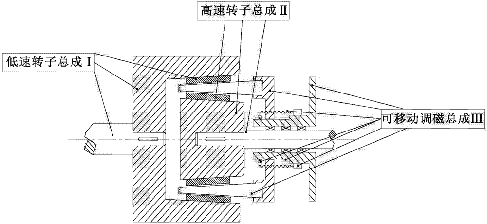
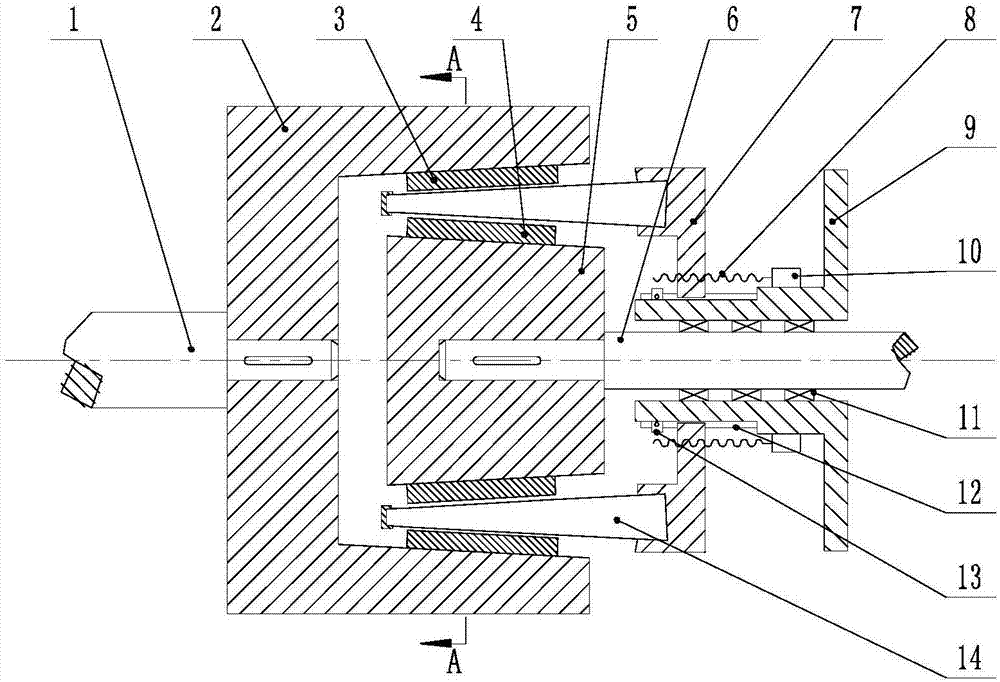
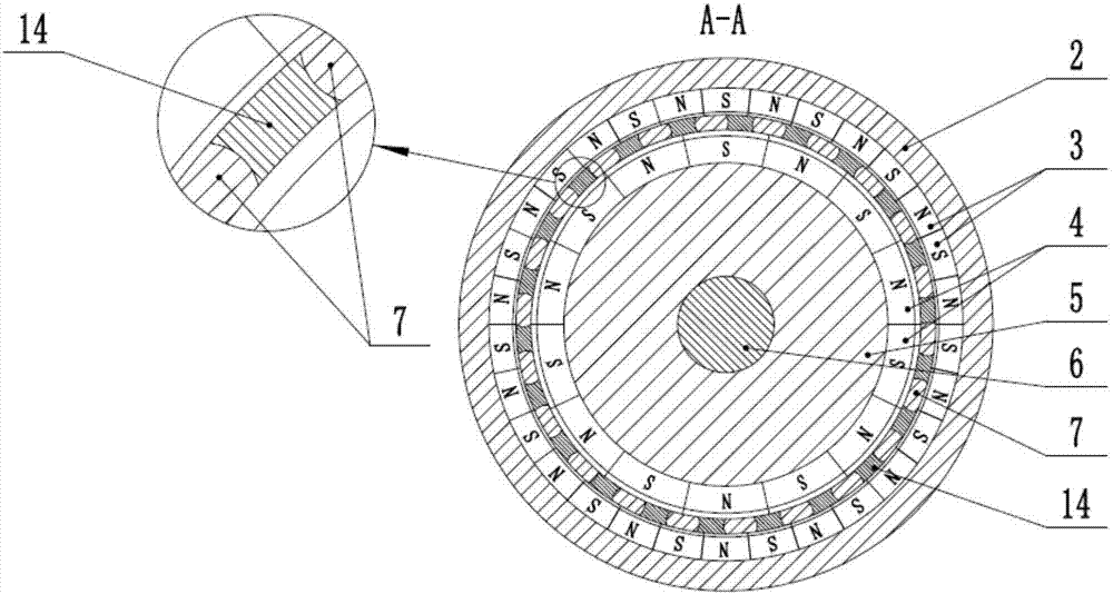
[0031] Such as figure 1 As shown, an air-gap adjustable magnetic gear using a side sinusoidal magnetic modulation device includes a low-speed rotor assembly I, a high-speed rotor assembly II, and a movable magnetic modulation assembly III; figure 2 , image 3 and Figure 4As shown, the low-speed rotor assembly I includes a low-speed shaft 1, an outer rotor base 2 and an outer rotor permanent magnet 3, wherein the right side of the low-speed shaft 1 is connected to the outer rotor base 2 through a common flat key, and the inner side of the outer rotor base 2 is The surface is inclined with respect to the outer surface on the right side of the outer rotor base 2, the inclination angle is β, and the value range of β is 5°-15°. The permanent magnets of the rotor 3 are closely arranged alternately by N poles and S poles, and the number of magnetic pole pairs is P 1 The high-speed rotor assembly II includes an inner rotor permanent magnet 4, an inner rotor base body 5 and a high...

Embodiment 2

[0036] The structure of this embodiment is basically the same as that of Embodiment 1, and the working principle is the same as that of Embodiment 1, such as Figure 10 , Figure 11 and Figure 12 As shown, the difference between the two is that in the present embodiment, the card slot 16 provided on the support frame 7 runs through the support frame, and the card notch 20 is formed on the support frame 7, and two sides of each card notch 20 are provided with A threaded hole, the magnetic adjustment device 14 formed by superimposing the positively rotating magnetic pole piece 17 on the side is installed into the card slot 16 through the card notch 20, and each card notch 20 is connected with a fastening block 19 through a bolt 18, and the fastening block The left side of 19 is in close contact with the magnetic adjustment device 14, clamping the magnetic adjustment device 14, thereby the magnetic adjustment device 14 can be sealed, and has both the magnetic adjustment and spe...


PUM


Abstract

The invention relates to the technical field of transmission in mechanical engineering, in particular to an air gap-adjustable magnetic gear with a side positive rotating magnetic adjusting device. The air gap-adjustable magnetic gear comprises a low-speed rotor assembly, a high-speed rotor assembly and a mobile magnetic adjusting assembly. The air gap-adjustable magnetic gear is characterized in that a servo motor is connected with a support frame through a lead screw, and the servo motor moves to drive the lead screw to move to achieve axial movement of the support frame; an outer rotor permanent magnet and an inner rotor permanent magnet are both obliquely arranged, and the magnetic adjusting device is formed by stacking side positive rotating type magnetic adjusting pole pieces and arranged in a clamp groove formed in the support frame in a clamped mode; and the magnetic adjusting device is driven by axial movement of the support frame to move axially to achieve the purpose of changing the size of an inner air gap and an outer air gap, and the upper surface and the lower surface of the magnetic adjusting device are parallel to the surface of the outer rotor permanent magnet and the surface of the inner rotor permanent magnet respectively, so that the inner air gap and the outer air gap change uniformly. According to the air gap-adjustable magnetic gear, by changing the size of the inner gap and the outer gap, the purposes of improving the transmission efficiency and increasing the torque density are achieved.

Description

technical field [0001] The invention relates to the technical field of transmission in mechanical engineering, and relates to a non-contact transmission magnetic gear, in particular to an air-gap adjustable magnetic gear using a side sinusoidal magnetic modulation device. It can be applied to non-contact transmission systems with large vibration, no leakage, high torque and high and low speed transmission. Background technique [0002] In the fields of industrial and agricultural production, national defense, aviation, aerospace and other fields, transmission mechanisms are required to realize power transmission and speed change at the same time. According to different applications, people have developed various conversion devices or equipment to meet the above requirements, such as chains, wire ropes, transmission belts, screw rods, crank connecting rods, slider mechanisms, cam ejector rod mechanisms, etc. In these conversion devices, the transmission mechanisms contact ea...

Claims


Application Information

Patent Timeline
Patent Type & Authority Applications(China)
IPC IPC(8): H02K49/10
CPCH02K49/102H02K49/106H02K2213/03H02K2213/09
Inventor 杨超君张威风柳康吴盈志刘明
Owner 重庆雨力机械有限公司
Why Eureka
Try Eureka