Road pedestrian recognition passing adjusting system and method for smart city
A pedestrian recognition and adjustment system technology, applied in the direction of road, road, character and pattern recognition, etc., can solve the problem of inability to control the opening and closing of each channel, the inability to obtain the turning distance and pedestrian flow, accurate and quantitative matching, etc. problems, to achieve the effect of maintaining the order of people flow, extending the length of the passage, and improving efficiency
- Summary
- Abstract
- Description
- Claims
- Application Information
AI Technical Summary
Problems solved by technology
Method used
Image

Examples
Embodiment 1
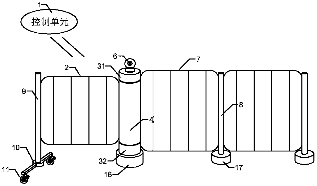
[0041] Such as Figure 1-5 As shown in the figure, a smart city road pedestrian recognition traffic adjustment system includes a current limiting fence, a turnstile and a control unit 1,
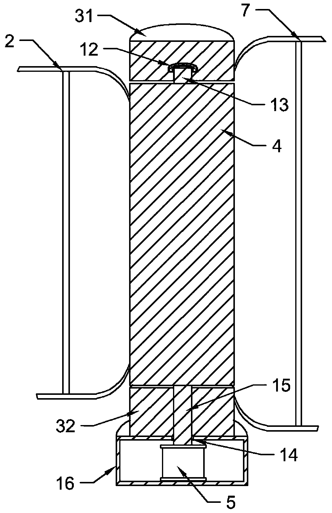
[0042] Several current-limiting passages are formed between the current-limiting fences, and a revolving fence gate is installed on the current-limiting fence at the entrance and exit of each current-limiting passage; the revolving fence gate includes a fence door body 2, a mounting column 3, a rotating shaft 4, and a motor , and a recognition camera 6 with a wireless Internet of Things communication function, the revolving fence gate is connected with the current-limiting fence through the installation column 3, and the rotating shaft 4 is arranged on the installation column 3 and connected with one end of the fence door body 2, and the motor 5 is connected with the rotating shaft 4 and drives the rotating shaft 4 to rotate to adjust the opening and closing of the fence door body 2 to the f...
Embodiment 2
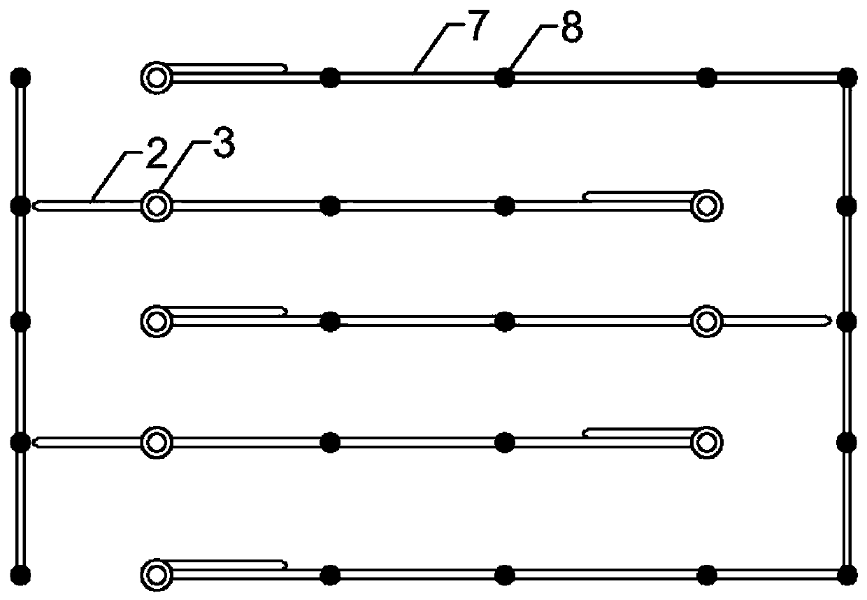
[0045] On the basis of the foregoing embodiments, as a further preferred solution: as figure 1 , Figure 3-5 As shown, the current-limiting barrier is composed of several barrier units 7 , and adjacent barrier units 7 are connected by columns 8 . Each fence unit 7 is detachably connected to the column 8, which is convenient for freely combining the length and shape of the flow-limiting fence.
Embodiment 3
[0047] On the basis of the foregoing embodiments, as a further preferred solution: as figure 1 As shown, the fence door body 2 is provided with a support column 9 at one end away from the rotating shaft 4, the bottom shaft of the support column 9 is connected with a rotatable pivot seat 10, and the bottom of the rotatable pivot seat 10 is provided with a universal wheel 11. Because the fence door body 2 or the revolving fence door itself has a certain weight, if only rely on the rotating shaft 4 for support in the process of driving and rotating, the wearing and tear of the rotating shaft 4 will be more serious, which will affect the service life of the revolving fence door. 9 and the rotatable pivot seat 10 and the universal wheel 11 can share the weight of a part of the revolving fence door. The universal wheel 11 is in contact with the ground. and the rotatable pivot seat 10 provided facilitates the adjustment of the positioning direction of the universal wheel 11, such as ...
PUM
 Abstract
Description
Claims
Application Information
 - R&D Engineer
- R&D Manager
- IP Professional
- Industry Leading Data Capabilities
- Powerful AI technology
- Patent DNA Extraction
Browse by: Latest US Patents, China's latest patents, Technical Efficacy Thesaurus, Application Domain, Technology Topic.
© 2024 PatSnap. All rights reserved.Legal|Privacy policy|Modern Slavery Act Transparency Statement|Sitemap