A ceiling structure without suspenders
A technology of suspended ceilings and suspenders, applied in ceilings, building components, building structures, etc., can solve the problems of poor adjustability, time-consuming and labor-intensive installation process, etc., and achieve the effects of enhancing overall performance, saving construction period, and simplifying procedures
- Summary
- Abstract
- Description
- Claims
- Application Information
AI Technical Summary
Problems solved by technology
Method used
Image
Examples
Embodiment 1
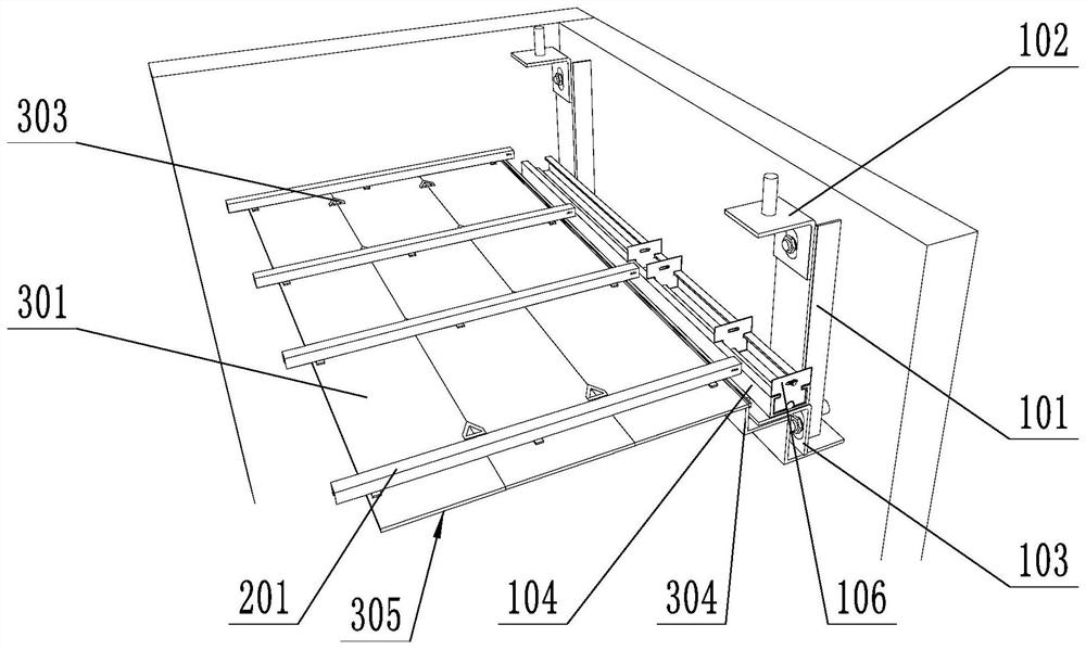
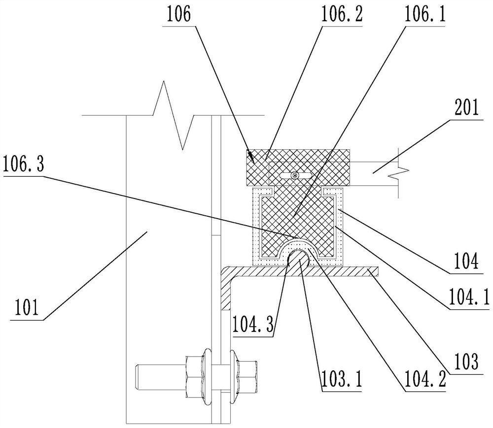
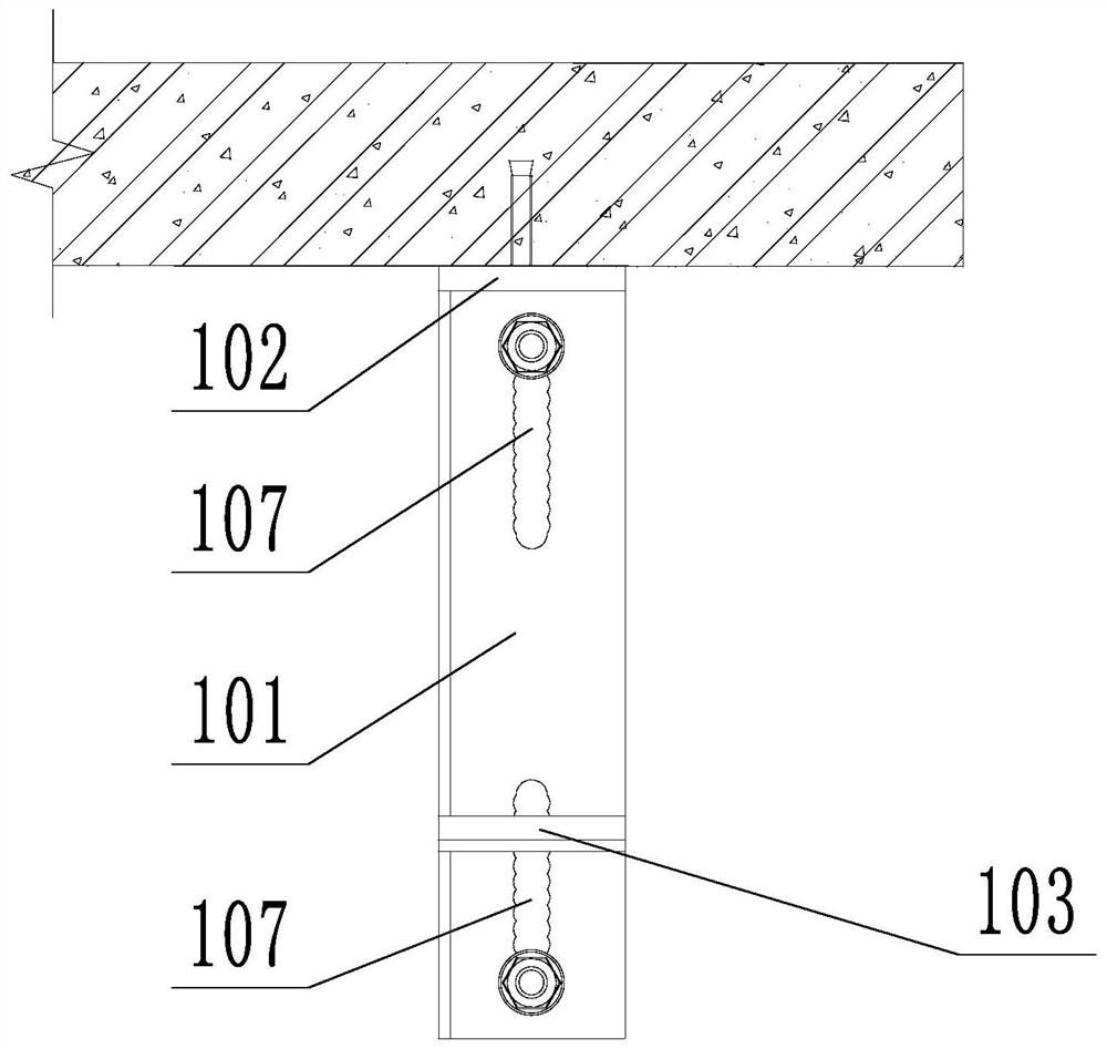
[0026] Such as figure 1 , figure 2 and image 3 As shown, a suspended ceiling structure without suspenders includes a suspended ceiling support structure and a decorative panel 305. The suspended ceiling support structure includes a vertical bar 101, an upper corner bracket 102, a lower corner bracket 103, a horizontal support 104, a keel 201, and a horizontal support 104 is a sliding plate 106 that is slidably connected; the vertical bar 101 is vertically arranged and fixed on the upper corner code 102, the vertical bar 101 is provided with a bar-shaped hole 107 of a wave-shaped structure, and the upper corner code 102 is provided with a bar-shaped hole 107 of a wave-shaped structure. shaped hole, the vertical bar 101 and the upper corner bracket 102 are fixed by fixing bolts, and one end of the fixing bolt passes through the strip hole 107; There is a sliding groove 104.1 on it, the sliding plate 106 includes a fixed part 106.1 and a sliding part 106.2, the sliding part 1...
Embodiment 2
[0029] Such as Figure 4 As shown, on the basis of the embodiment, the keel 201 and the buckle 202, the keel 201 is integrally formed, the keel 201 includes a body part 201.1, a connecting part 201.2 and a buckle part 201.3; the body part 201.1 includes two transverse The plate part 201.1.1 and the two vertical plate parts 201.1.2, the two horizontal plate parts 201.1.1 and the two vertical plate parts 201.1.2 are arranged alternately, and are sequentially connected to form a square body part 201.1; the vertical plate part 201.1 One end of .2 extends outward to form a connecting portion 201.2, and one end of the connecting portion 201.2 extends toward the body portion 201.1 to form a fastening portion 201.3; the fastening portion 201.3 bends toward the body portion 201.1 to form a first barb structure 201.4; The number of the first barb structure 201.4 is one, the two first barb structures 201.4 are arranged symmetrically and the two fastening parts 201.3 are arranged between ...
Embodiment 3
[0032] Such as Figure 5 and Figure 6 As shown, the decorative panel 305 includes a standard panel 301 and an adapter panel 304. The corresponding side of the standard panel 301 is an inclined surface, and the two inclined surfaces are parallel to each other. One side is a bevel, and the adapter panel 304 is provided with a clip 302 on the inclination, and the inclination of the adapter panel 304 is adapted to the inclination of the standard panel 301; the adapter panel 304 and the standard panel 301 are connected to form a complete decorative panel 305 , the decorative panel 305 is provided with fastening pieces 202, the fastening pieces 202 are fixed to the decorative panel 305, and a plurality of fastening pieces 202 are distributed in rows; the extension direction of the keel 201 is perpendicular to the extension direction of the standard panel 301, as shown in the figure As shown, the buckle 202 is clamped with the keel 201;
[0033] One end of the clamping piece 302 i...
PUM
 Abstract
Description
Claims
Application Information
 - R&D
- Intellectual Property
- Life Sciences
- Materials
- Tech Scout
- Unparalleled Data Quality
- Higher Quality Content
- 60% Fewer Hallucinations
Browse by: Latest US Patents, China's latest patents, Technical Efficacy Thesaurus, Application Domain, Technology Topic, Popular Technical Reports.
© 2025 PatSnap. All rights reserved.Legal|Privacy policy|Modern Slavery Act Transparency Statement|Sitemap|About US| Contact US: help@patsnap.com


