Firmly-fixed mechanical measuring tripod

A mechanical, tripod technology, applied in the direction of mechanical equipment, machine/stand, camera body, etc., can solve the problems of stand shaking, difficult to balance adjustment, affecting the effect of measurement, etc., to achieve support height improvement, balance adjustment is convenient , the effect of easy adjustment

Active Publication Date: 2020-02-18
YELLOW RIVER CONSERVANCY TECHN INST
View PDF7 Cites 6 Cited by
  • Summary
  • Abstract
  • Description
  • Claims
  • Application Information

AI Technical Summary

Problems solved by technology

Most of the measuring brackets in the prior art are relatively heavy and inconvenient to carry, and it is difficult to adjust the balance on rough roads, which affects the measurement effect and causes troubles for the measurers. At the same time, when measuring on some muddy roads or land, Due to the soft ground and lack of stability, the bracket shakes seriously, resulting in inclination and affecting the measurement results. Therefore, we urgently need a fixed mechanical measuring tripod to solve the above problems

Method used


Image

  • Firmly-fixed mechanical measuring tripod
  • Firmly-fixed mechanical measuring tripod
  • Firmly-fixed mechanical measuring tripod

Examples


Embodiment 1

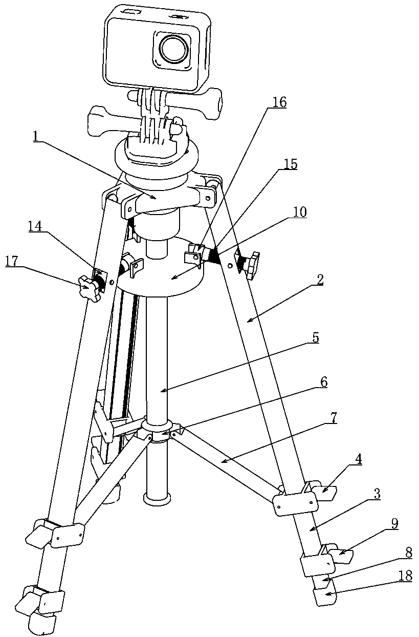
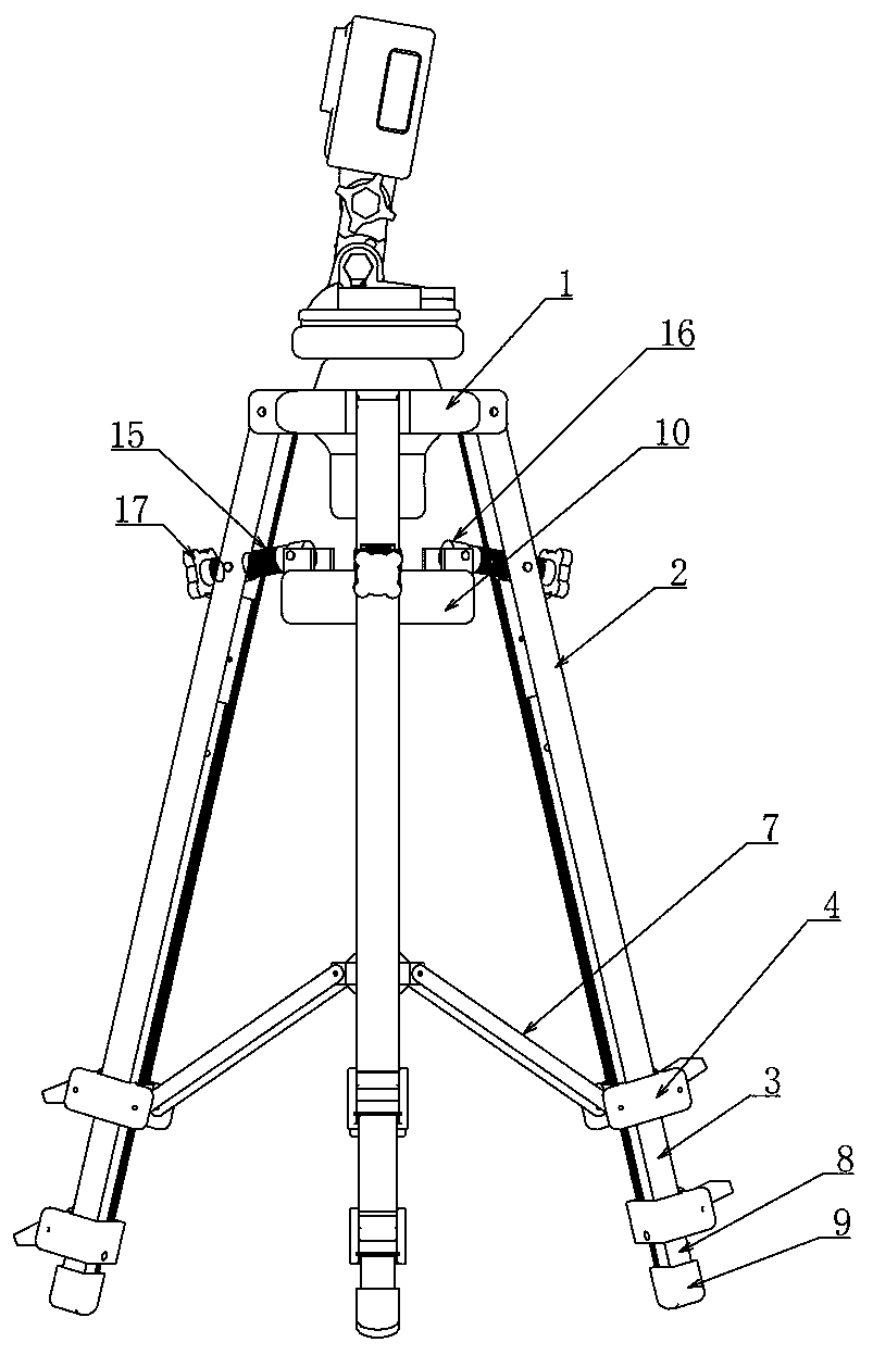
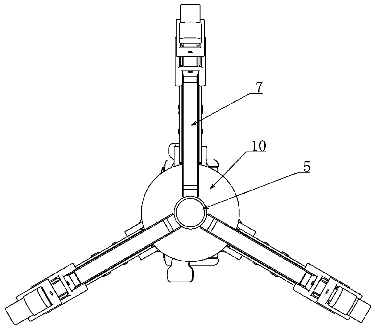
[0027] Example one, combined with Figure 1-11 , A firmly fixed mechanical measuring tripod, comprising a measuring table 1, a measuring bracket is connected to the measuring table 1, and a camera is connected to the measuring bracket, characterized in that the lower end of the measuring table 1 is hinged with three sets of support rods 2, and the measuring table 1 The outer edges are evenly distributed and hinged with three groups of support rods 2, and the three groups of said support rods 2 are slidingly fitted with three groups of sliding rods 3. Removable connection, the upper pull-type buckle 4 is shown in the figure. Pulling the position of the rotating wrench on the upper pull buckle can change the sliding-locking state between the slide bar 3 and the support bar 2. This pull The buckle belongs to the prior art and is very common in daily life. I will not repeat it here. The lower end of the measuring table 1 is connected with a positioning rod 5, and the positioning ro...

Embodiment 2

[0028] The second embodiment, on the basis of the first embodiment, combined with the attached Figure 1-11 , The balance adjustment device includes a transparent balance plate 10 connected to the upper end of the positioning rod 5, the balance plate 10 is vertically spaced with two sets of radially arranged receiving grooves 11, the receiving grooves 11 along the The balance plate 10 is arranged in the diameter direction and is symmetrical along the center of the balance plate 10. The two groups of accommodating grooves 11 are arranged along the vertical direction, and they are not connected to each other in the vertical direction. The two ends of the accommodating groove 11 are respectively connected with springs 12. One end of the accommodating groove 11 connected to one end of the two sets of springs 12 is far from the center of the balance plate 10, and the other end is freely arranged in the same accommodating groove 11. The two sets of springs 12 are in contact with a dr...

Embodiment 3

[0029] The third embodiment, on the basis of the second embodiment, combined with the attached Figure 1-11 , The support rod 2 is hinged with a sleeve 14, and the support rod 2 is provided with a through hole extending along the radial direction of the balance plate 10, and the sleeve 14 is hinged in the through hole and is connected to the balance plate along the support rod 2. The articulation is performed in a vertical plane formed by the radial direction of 10, and the internal thread of the sleeve 14 is matched with a screw 15 arranged radially along the balance plate 10. The sleeve 14 has internal threads, and the screw 15 is screwed. There are external threads on the middle part of the two, and the two are threaded together. The outer edge of the upper end of the balance plate 10 is evenly distributed in the circumferential direction and hinged with three sets of shaft sleeves 16, the three sets of shaft sleeves 16 and the ends of the corresponding screw 15 The shaft sl...


PUM


Abstract

The invention relates to a firmly-fixed mechanical measuring tripod. By using an upper pulling type buckle and a lower pulling type buckle for clamping in cooperation with supporting rods, sliding rods and supporting legs, the locking function is realized, and the supporting height is further increased; meanwhile, by adding a balance plate to a positioning rod, balance is observed through a driving ball matched in the balance plate, and balance is fine adjusted by screwing a stud, so a measuring table is in a precise balance state; through the cooperation of multiple groups of cylindrical pins, rectangular blocks and driving pins at the lower ends of the supporting legs, the multiple groups of conical supporting rods in a supporting device are inserted in the ground to support the whole measuring tripod when the ground of a measuring site is muddy or soft, and adjustment is convenient; and the tripod is made of light aluminum alloy or carbon steel, so the tripod is convenient to carry,firm in supporting, suitable for various different terrains, beneficial for balance adjustment, excellent in effect, high in practicability and suitable for use and popularization.

Description

Technical field [0001] The invention belongs to the technical field of measuring equipment, and in particular relates to a mechanical measuring tripod with firm fixation. Background technique [0002] Surveying is the most commonly used positioning method in engineering technology. Most of the measurement brackets in the prior art are bulky, inconvenient to carry, and difficult to balance adjustment on rugged roads, which affects the measurement effect and causes troubles to the surveyor. At the same time, when measuring on some muddy roads or ground, Due to the soft ground and lack of stability, the support shakes severely, which leads to tilt and affects the measurement effect. Therefore, we urgently need a fixed and firm mechanical measurement tripod to solve the above problems. Summary of the invention [0003] In view of the shortcomings of the prior art, the purpose of the present invention is to provide a firm-fixed mechanical measuring tripod to solve the problems mention...

Claims


Application Information

Patent Timeline
Patent Type & Authority Applications(China)
IPC IPC(8): F16M11/32F16M11/04G03B17/56
CPCF16M11/32F16M11/043G03B17/56
Inventor 曹永娣牛贺洋聂松广李忠旺马晓慧卫宗超雷恒张宏祥刘小红王艳凤薛冰
Owner YELLOW RIVER CONSERVANCY TECHN INST
Why Eureka
Try Eureka