A Measuring Point Arrangement Method Applicable to Hypersonic Flight Test Transition Research

A technology for measuring point layout and flight test, applied in the direction of measuring device, aerodynamic test, machine/structural component test, etc.

Active Publication Date: 2021-02-09
BEIJING LINJIN SPACE AIRCRAFT SYST ENG INST +1
View PDF9 Cites 0 Cited by
  • Summary
  • Abstract
  • Description
  • Claims
  • Application Information

AI Technical Summary

Problems solved by technology

[0007] The problem solved by the technology of the present invention is: in view of the lack of theoretical research on the transition of hypersonic vehicles and the fact that ground wind tunnel tests cannot meet the needs of transition research, it is necessary to measure transition data from flight tests to provide support for transition theory research and method improvement. The invention proposes a measuring point arrangement method suitable for hypersonic transition research, which can be effectively used for measuring point arrangement in transition research

Method used


Image

  • A Measuring Point Arrangement Method Applicable to Hypersonic Flight Test Transition Research
  • A Measuring Point Arrangement Method Applicable to Hypersonic Flight Test Transition Research
  • A Measuring Point Arrangement Method Applicable to Hypersonic Flight Test Transition Research

Examples


Embodiment 1

[0048]Example 1: Arrangement of a small number of transition points

[0049]A small number of measurement points focus on the limited transition information. The conventional ones are mainly divided into the main flow direction measurement point layout and the cross flow direction measurement point layout. The general location and direction of the measurement point layout depend on the needs of transition research.

[0050]The through-wall sensor can directly measure the physical quantity of the aircraft surface, and the through-wall sensor is selected for transition measurement. At the same time, the thermophysical parameters of the sensor "density × specific heat capacity × thermal conductivity" should be as close as possible to the surface of the aircraft. Compared with the surface material value of the aircraft, it should be less than 30%.

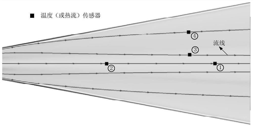
[0051]image 3 Among the four measuring points shown, measuring point ① and measuring point ② are main flow direction measuring points, and measuring...

Embodiment 2

[0055]Example 2: Arrangement of a large number of transition points

[0056]In the case of a large number of measuring points, such asFigure 4As shown, the measurement points are properly arranged to obtain sufficient transition information, such as the starting position of the transition, the length of the transition zone and the shape of the transition array, etc. Generally, at least 3 to 4 are arranged in the transition zone. Measuring points;

[0057]The through-wall sensor can directly measure the physical quantity of the aircraft surface, and the through-wall sensor is selected for transition measurement. At the same time, the thermophysical parameters of the sensor such as "density × specific heat capacity × thermal conductivity" should be as close as possible to the surface of the aircraft. The above-mentioned thermophysical parameters The square root should be less than 30% compared to the value of the aircraft surface material.

[0058]The number of measuring points is large, and t...


PUM


Abstract

A measurement point arrangement method suitable for hypersonic flight test transition research, which is realized in the following manner: S1. According to the measurement requirements, determine whether to measure natural transition or forced transition. If it is to measure natural transition, go to S2 ; If it is a forced transition, turn to S3; S2, measure the transition of the mainstream and or the transition of the cross-flow effect according to the measurement requirements, wherein when measuring the transition of the mainstream, the measuring point is arranged on the streamline in the direction of the mainstream of the hypersonic vehicle When measuring the transition situation of the cross-flow effect, the measuring point is arranged on the position with the cross-flow velocity in the lateral direction; the main flow direction is the streamline direction of the center of the aircraft and the streamline direction with an angle of no more than 3°; S3, Rough elements are set at pre-determined positions on the aircraft, and measuring points are arranged downstream of the streamline where the rough elements are located; above-mentioned measuring point positions are implemented by installing sensors to measure the physical quantities of the aircraft surface during the flight test.

Description

Technical field[0001]The invention belongs to the field of spacecraft transition research.Background technique[0002]Transition refers to the process of changing the flow state from laminar flow to turbulent flow. The physical mechanism is that as the Reynolds number increases, laminar flow becomes unstable, leading to continuous growth of disturbances in the flow, and then complex nonlinear disturbances and vortices The fragmentation of the structure and the vortex eventually causes the flow to evolve into a chaotic state (ie, a turbulent state). When the boundary layer transitions, the surface of the aircraft will transition from laminar heating to turbulent heating, and the surface heat flow will increase several times, causing significant changes in the surface thermal environment.figure 1 Given the changes in the surface heat flow of the reentry vehicle during the transition, it can be seen that when the transition occurs, the surface heat flow increases by about 3 times. Theref...

Claims


Application Information

Patent Timeline
Patent Type & Authority Patents(China)
IPC IPC(8): G01M9/06
CPCG01M9/06
Inventor 聂亮李宇周禹刘国仟刘宇飞袁野聂春生赵晓利赵良曹占伟朱广生
Owner BEIJING LINJIN SPACE AIRCRAFT SYST ENG INST
Why Eureka
Try Eureka