
An anti-vibration self-resetting satellite antenna support rod structure

A satellite antenna and self-resetting technology, applied in flexible antennas, folded antennas, etc., can solve problems such as coupling resonance, severe vibration, and low natural frequency, and achieve good signal transmission stability, avoid residual deformation, and structural form simple effect

Active Publication Date: 2021-10-15
BEIJING UNIV OF TECH
View PDF0 Cites 0 Cited by
  • Summary
  • Abstract
  • Description
  • Claims
  • Application Information

AI Technical Summary

Problems solved by technology

However, the structural shape of the satellite antenna has very significant differences and time-varying properties from the retracted state to the deployed state, which leads to the dynamic characteristics of the drive control system during the antenna deployment process and the time-varying dynamic characteristics of the satellite dynamic characteristics and the antenna structure during the deployment process. It is easy to be coupled and generate severe vibration, which brings difficulties to the design of the drive system
The structural shape of the large-scale flexible self-deploying antenna changes continuously during the deployment process and is a multi-degree-of-freedom multi-mode vibration system. Due to the weak stiffness and low natural frequency of the large-scale deployment size, coupling resonance is prone to occur during the deployment process, antenna locking action and attitude control engine Dynamic interference will also produce random vibrations in a wide frequency band. Satellite antennas still have to withstand many vibration excitations during the orbital phase. Although these vibration excitations are not large in magnitude, they are likely to affect the normal operation of key components of the antenna.
Traditional passive vibration control methods are difficult to reliably and effectively control the multi-degree-of-freedom and multi-mode time-varying structural vibrations during the entire deployment process of the antenna, while the active vibration control methods developed in recent years cannot avoid the shortcomings of the closed-loop control model being difficult to accurately establish and control time delay. The effect of vibration control in practical applications is greatly reduced

Method used


Image

  • An anti-vibration self-resetting satellite antenna support rod structure
  • An anti-vibration self-resetting satellite antenna support rod structure
  • An anti-vibration self-resetting satellite antenna support rod structure

Examples


Embodiment Construction

[0017] The present invention will be further described below in conjunction with the accompanying drawings and specific embodiments.

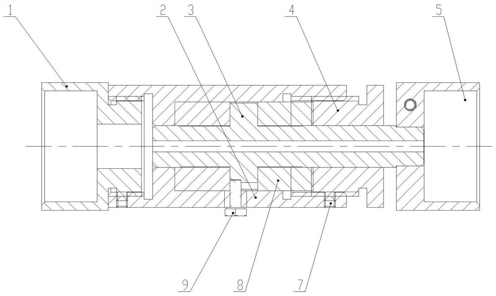
[0018] The anti-vibration self-resetting satellite antenna support rod structure proposed by the present invention is as follows: Figure 5 As shown, it includes four parts: a self-resetting projectile friction damping member 12, a scroll spring 13, a carbon fiber rod 11, and a hinge 10; Frictional energy consumption controls the axial vibration of the unfolding member; the scroll spring 13 provides the driving force for deploying the antenna support rod; the hinge 10 and the carbon fiber rod 11 jointly connect various parts, making the whole device a whole.

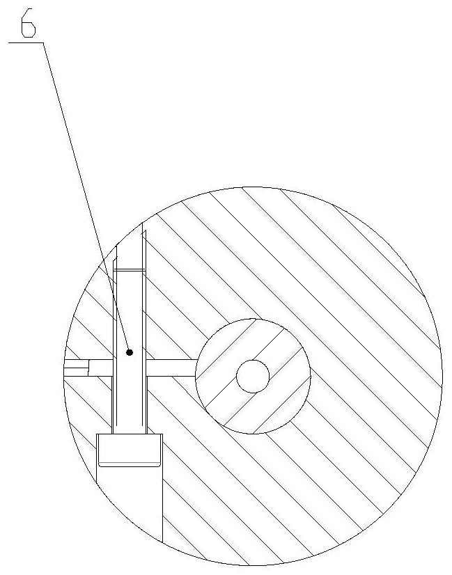
[0019] Specifically, the control member of the self-resetting elastic support friction damping structure proposed by the present invention is as follows: Figure 1 to Figure 4 As shown, it includes: external thread connector 1, outer cylinder 2, inner cylinder 3, adjusting bolt 4, intern...


PUM


Abstract

The invention discloses an anti-vibration self-resetting satellite antenna support rod structure, comprising a self-resetting elastic friction damping member for controlling the axial vibration of a deployment member, a scroll spring for providing a driving force for the deployment of the antenna support rod, and a Hinge with carbon fiber rod. The self-resetting elastic support friction damping structure control member has the same axis line, the inner cylinder baffle is provided with grooves, the radial movement is limited by limit screws, and the two symmetrically arranged hexagon socket set screws play a clamping role , used to prevent it from moving axially; two metal rubber blocks that play the role of energy dissipation are placed between the inner cylinder and the outer cylinder, symmetrically distributed on both sides of the inner cylinder baffle; one end of the inner cylinder is connected to the inner threaded connector At the same time, the inner threaded connector is connected to the carbon fiber rod; the other ends of the outer cylinder and the inner cylinder are connected to the outer threaded connector. When the inner cylinder and the outer cylinder move relative to each other due to vibration, the axial vibration of the deployment member is suppressed by the frictional energy dissipation of the metal rubber block.

Description

technical field [0001] The invention relates to the technical field of large-scale flexible self-deploying antenna structures, in particular to an anti-vibration self-resetting satellite antenna support rod structure. Background technique [0002] With the development of aerospace, communication and other industries, antennas, as an important means of transmitting electromagnetic wave signals, are more and more widely used in various fields. Due to the limitation of the space and capacity of the spacecraft, the large antenna should be sent into space in a folded state, and after reaching the predetermined orbit, it will be unfolded into the required geometric configuration after receiving instructions. In order to ensure that the large-scale self-deploying antenna not only meets the carrying conditions, but also ensures high resolution and high stability, the structural characteristics of the large-scale self-deploying antenna in space need to have light weight, high deploym...

Claims


Application Information

Patent Timeline
Patent Type & Authority Patents(China)
IPC IPC(8): H01Q1/08
CPCH01Q1/08H01Q1/085
Inventor 王民刘佳星刘钦达赵婷婷
Owner BEIJING UNIV OF TECH
Learn More