Mowing head
A technology for cutting grass heads and grass ropes, applied in the field of grass cutting heads, can solve the problems of reducing work efficiency, reducing user experience, time-consuming and labor-intensive, etc.
- Summary
- Abstract
- Description
- Claims
- Application Information
AI Technical Summary
Problems solved by technology
Method used
Image
Examples
Embodiment 1
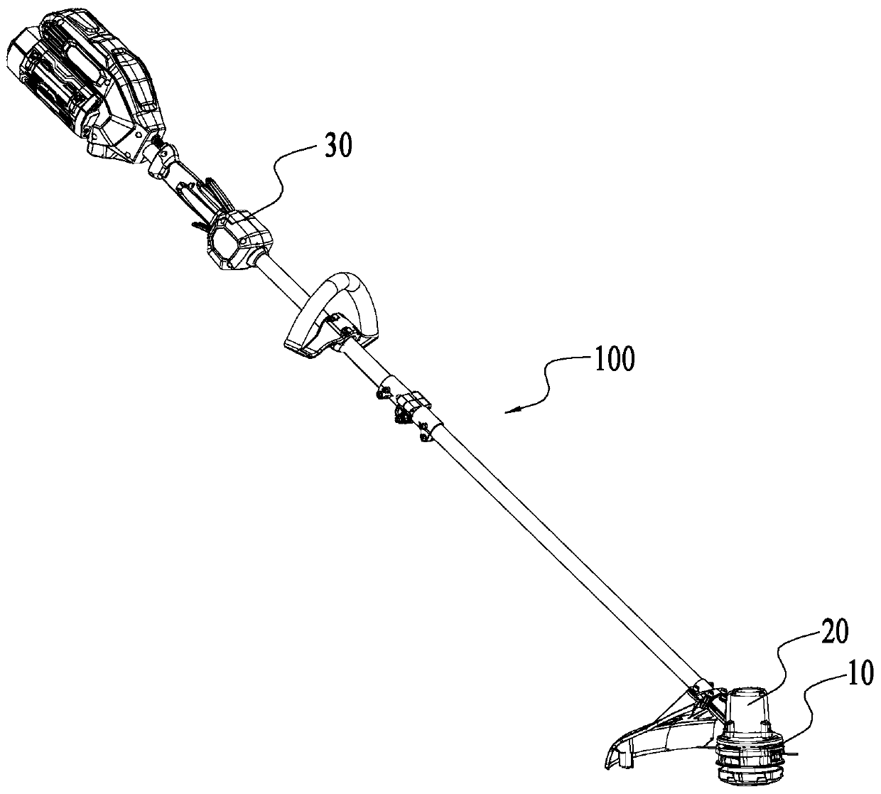
[0046] figure 1 Shown is a schematic structural view of a mowing machine 100 in an embodiment. In this embodiment, the mowing machine 100 includes a mowing head 10 , a driving device 20 and an operating device 30 .
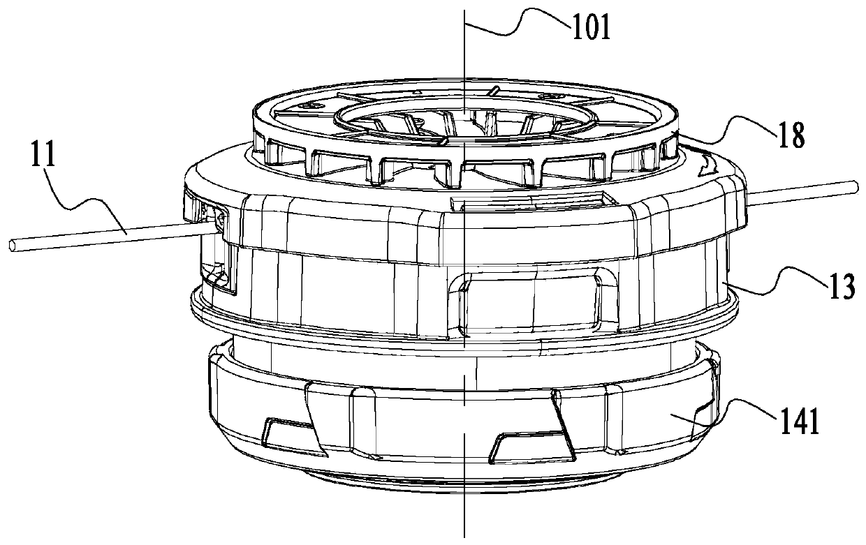
[0047] Such as figure 1 and figure 2 As shown, the driving device 20 can drive the mowing head 10 to rotate around the first axis 101, thereby driving the mowing rope 11 to rotate and cut vegetation. The operating device 30 is used for a user to operate to control the mower 100 .
[0048] The drive device 20 includes a motor and a drive shaft. Wherein, the driving shaft is connected to the mowing head 10 so as to drive the mowing head 10 to rotate around the first axis 101 .
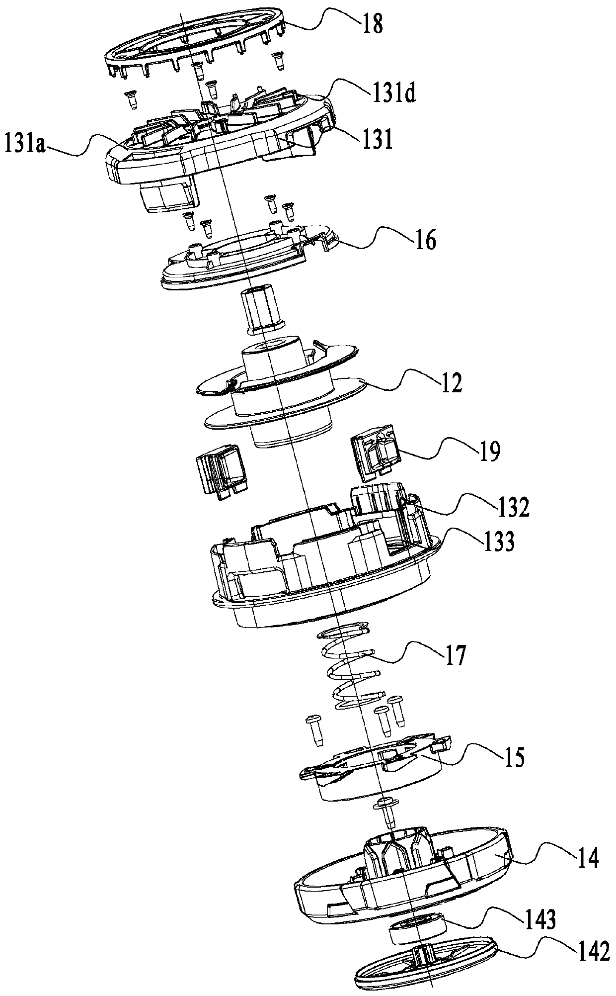
[0049] Such as figure 2 and image 3As shown, the mowing head 10 includes a bobbin 12 and a head shell 13, the bobbin 12 is used to wind the mowing rope 11 and is accommodated in the head shell 13, the bobbin 12 is provided with a winding groove 127 (refer to Figure 7 );Such as i...
Embodiment 2
[0069] In an embodiment, the first guiding structure can also be connected to other positions of the head shell, such as Figure 13 to Figure 14 The structure of the grass cutting head in the second embodiment is shown. In this embodiment, the grass cutting head has the same driving device and operating device as in the first embodiment. Only the differences between the first embodiment and the first embodiment are introduced below. structure.
[0070] Figure 13 The upper side and the lower side are defined in the middle. In this embodiment, the third guide 41 is connected to the second housing 42 through a fixing member, and is located between the bobbin 43 and the intermediate piece 44. The structure of the third guide 41 The structure of the first guide structure 16 in the first embodiment is the same, only the position and orientation are different; the fourth guide 45 is located on the second stop portion of the bobbin 43, and the structure of the fourth guide 45 is the...
Embodiment 3
[0072] In one embodiment, the mower has the same driving device and operating device as those in the first embodiment, and only the different structures in this embodiment and the first embodiment will be introduced below. Such as Figure 15-Figure 17 The mowing head 50 of the mowing machine in the third embodiment is shown. In this embodiment, the head shell includes a first housing part 51 and a second housing part 52 . The first guiding structure 521 is disposed on the second housing part 52, and the second housing part 52 is specifically an end away from the driving device. The second guiding structure 531 is disposed on the bobbin 53 and is disposed on a side close to the first guiding structure 521 . The first guiding structure 521 is fixedly connected or integrally formed with the second casing part 52 . The first guiding structure 521 has the same guiding area 521a through which the mowing rope can pass, a temporary storage area 521b for the mowing rope and a rotatin...
PUM
 Abstract
Description
Claims
Application Information
 - R&D
- Intellectual Property
- Life Sciences
- Materials
- Tech Scout
- Unparalleled Data Quality
- Higher Quality Content
- 60% Fewer Hallucinations
Browse by: Latest US Patents, China's latest patents, Technical Efficacy Thesaurus, Application Domain, Technology Topic, Popular Technical Reports.
© 2025 PatSnap. All rights reserved.Legal|Privacy policy|Modern Slavery Act Transparency Statement|Sitemap|About US| Contact US: help@patsnap.com


