
Efficient gas-liquid separator for chemical engineering production

A gas-liquid separator, chemical production technology, applied in liquid separation, separation method, dispersed particle separation and other directions, can solve the problems of gas-liquid separator corrosion, waste of mechanical energy and other problems

Active Publication Date: 2020-02-21
江苏华洋新思路能源装备股份有限公司
View PDF18 Cites 2 Cited by
  • Summary
  • Abstract
  • Description
  • Claims
  • Application Information

AI Technical Summary

Problems solved by technology

When the traditional gas-liquid separator processes the gas containing condensed liquid with a fast flow rate, due to the fast flow rate of the gas containing condensed liquid, it directly enters the gas-liquid separator to flush the equipment in it, which is very easy to make the gas-liquid separator Corrosion occurs inside, and the mechanical energy carried by the high-speed condensate-containing gas is wasted. Therefore, according to the principle of gravity sedimentation, we propose a high-efficiency gas-liquid separator for chemical production

Method used


Image

  • Efficient gas-liquid separator for chemical engineering production
  • Efficient gas-liquid separator for chemical engineering production
  • Efficient gas-liquid separator for chemical engineering production

Examples


Embodiment Construction

[0021] The following will clearly and completely describe the technical solutions in the embodiments of the present invention with reference to the accompanying drawings in the embodiments of the present invention. Obviously, the described embodiments are only some, not all, embodiments of the present invention. Based on the embodiments of the present invention, all other embodiments obtained by persons of ordinary skill in the art without making creative efforts belong to the protection scope of the present invention.

[0022] In describing the present invention, it should be understood that the terms "upper", "lower", "front", "rear", "left", "right", "top", "bottom", "inner", " The orientation or positional relationship indicated by "outside", etc. is based on the orientation or positional relationship shown in the drawings, and is only for the convenience of describing the present invention and simplifying the description, rather than indicating or implying that the referre...


PUM


Abstract

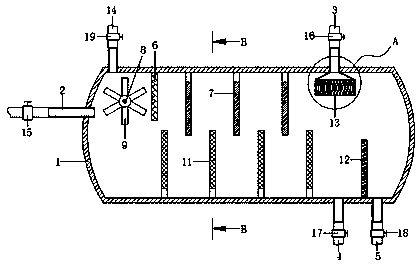
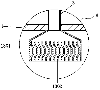
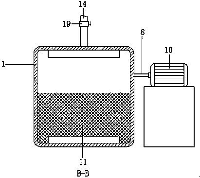
The invention discloses an efficient gas-liquid separator for chemical engineering production. The efficient gas-liquid separator comprises a horizontal tank, a gas inlet pipe is arranged on the leftsidewall of the horizontal tank, a gas outlet pipe is arranged at the right side of the top of the horizontal tank, a left liquid outlet pipe and a right liquid outlet pipe are arranged at the right side of the bottom of the horizontal tank, a baffle plate and uniformly-distributed upper wave-proof plates are arranged at the top of the inner cavity of the horizontal tank, the upper wave-proof plates are positioned between the baffle plate and the gas outlet pipe, a rotating shaft is arranged on the rear sidewall of the horizontal tank in a penetrating manner through a sealing bearing, impellers are arranged on the outer wall of one end, in the horizontal tank cavity, of the rotating shaft, one end, located outside the horizontal tank, of the rotating shaft is connected to an electric generator, uniformly-distributed lower wave-proof plates and an overflow partition plate are arranged at the bottom of the inner cavity of the horizontal tank, the lower wave-proof plates are located at the left side of the overflow partition plate, a mist catcher is arranged at a position, located at the bottom of the gas inlet end of the gas outlet pipe, of the top of the inner cavity of the horizontal tank, and a water inlet pipe is arranged at the left side of the top of the horizontal tank. When gas-liquid separation is performed, the reasonably combined electric generator is applied to utilize a condensate-containing gas to generate electricity.

Description

technical field [0001] The invention relates to the technical field of gas-liquid separators, in particular to a high-efficiency gas-liquid separator for chemical production. Background technique [0002] The main function of the gas-liquid separator is to process the gas containing condensate, to realize the function of condensate recovery or gas purification. According to different principles, it can be divided into gravity sedimentation, flow separation, centrifugal force separation, packing separation, wire mesh separation, Different types of gas-liquid separators such as microporous filtration separation. When the traditional gas-liquid separator processes the gas containing condensed liquid with a fast flow rate, due to the fast flow rate of the gas containing condensed liquid, it directly enters the gas-liquid separator to flush the equipment in it, which is very easy to make the gas-liquid separator Corrosion occurs inside the gas and wastes the mechanical energy ca...

Claims


Application Information

Patent Timeline
IPC IPC(8): B01D17/028B01D17/032B01D45/04F01D15/10
CPCB01D17/0211B01D17/0214B01D45/04F01D15/10
Inventor 朱广华方旭高胜红褚玉华王芳
Owner 江苏华洋新思路能源装备股份有限公司
Learn More