
Automatic stationery clamp assembling equipment

A technology for automatic assembly and stationery clips, which can be used in assembly machines, workpiece clamping devices, metal processing equipment, etc., and can solve the problems that the clips cannot be placed stably on the side and are not suitable for assembly.

Pending Publication Date: 2020-02-21
义乌市宏日智能科技有限公司
View PDF3 Cites 5 Cited by
  • Summary
  • Abstract
  • Description
  • Claims
  • Application Information

AI Technical Summary

Problems solved by technology

The width of the pressing part 91 is much smaller than the width of the clamping part 92, resulting in that the side of the clip is not flat, and the clip cannot be placed stably on its side
The above clip assembly machine is not suitable for assembling clips whose sides are not flat

Method used


Image

  • Automatic stationery clamp assembling equipment
  • Automatic stationery clamp assembling equipment
  • Automatic stationery clamp assembling equipment

Examples


Embodiment Construction

[0060] The present invention will be described in further detail below in conjunction with the accompanying drawings.

[0061] This specific embodiment is only an explanation of the present invention, and it is not a limitation of the present invention. Those skilled in the art can make modifications to this embodiment without creative contribution as required after reading this specification, but as long as they are within the rights of the present invention All claims are protected by patent law.

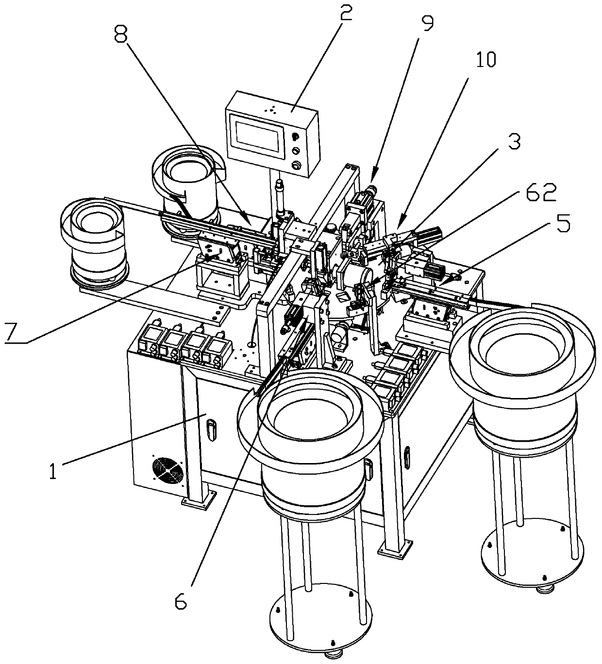
[0062] An automatic stationery folder assembly equipment includes a frame 1, a power device (not shown in the figure) is installed in the frame 1, and the power device can use a motor. A splitter 50 is installed on the clip base 4, and the input shaft 51 of the splitter 50 is connected with the power unit through a chain or a belt transmission. The rotating disk 3 is installed on the output shaft 52 of the divider 50 , and the power unit drives the rotating disk 3 to rotate inter...


PUM


Abstract

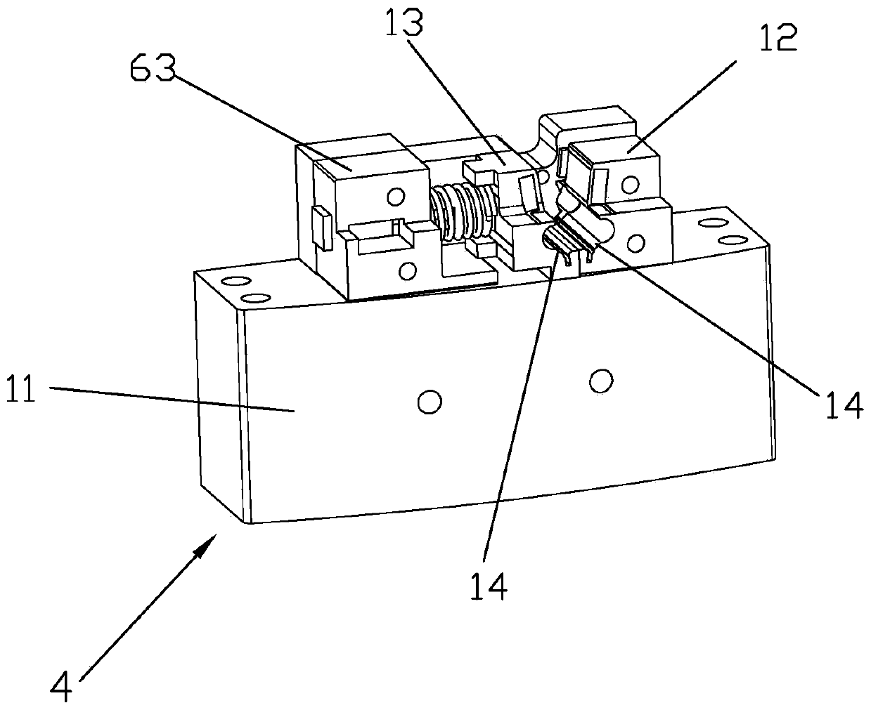
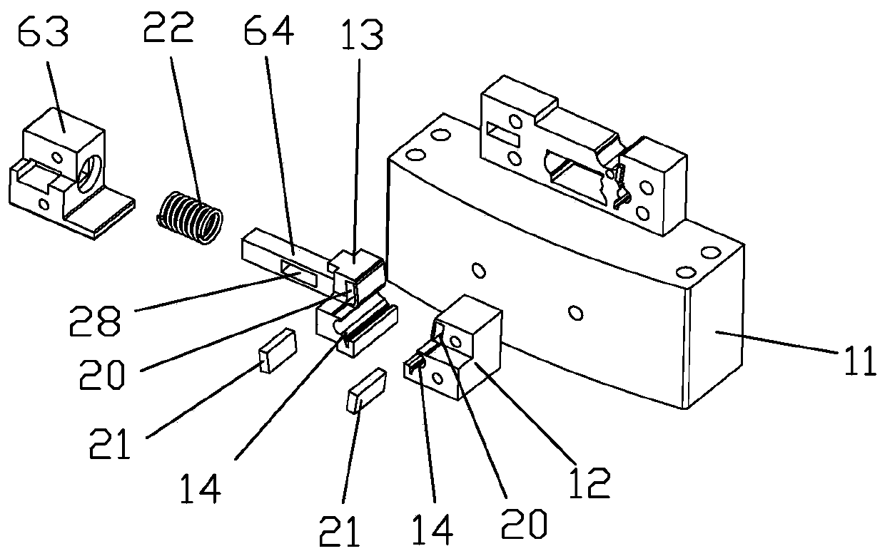
The invention discloses automatic stationery clamp assembling equipment which comprises a rack. A controller and a rotating disc are arranged on the rack. A clamp base is installed on the rotating disc. A first clamp piece mounting device, a second clamp piece mounting device, a torsional spring mounting device, a pin mounting device, a pin pressing device and a take-out device are installed at the portion, at the outer side of the rotating disc, of the rack. The clamp base comprises a base body. A first clamp piece base and a second clamp piece base are arranged on the base body. The first clamp piece base and the second clamp piece base are each provided with a clamp piece placement groove. The clamp piece placement grooves extend in the width direction of clamp pieces, the two clamp piece placement grooves are inclined to the two sides of the vertical direction, and the second clamp piece base is located at one side of the first clamp piece base and can move away from the first clamp piece base. According to the clamp assembling equipment, by changing the structure of the clamp base, the other devices are correspondingly changed at the same time, clamp pieces can be spliced in the lateral direction, and therefore clamp pieces which cannot lie on the side stably can be assembled.

Description

technical field [0001] The invention relates to the technical field of clip assembly machines, in particular to an automatic stationery clip assembly device. Background technique [0002] Clips are commonly used clamping tools in daily life. Currently, most clips are assembled by clip assembly machines. As shown in the Chinese patent No. 201711482682.4, it includes a rotating disc, which is driven to rotate by a divider. A plurality of clamping seats are evenly distributed on the circumference of the rotating disk, and a plurality of stations are arranged on the frame outside the clamping seats facing the clamping seats. Two clip mounting devices, a spring pin mounting device, and a press Riveting device and pick-up device. [0003] When the above-mentioned assembly machine assembles the clips, the clips are placed sideways, and when the clips are fed into the clip seat, the clips are first stacked vertically above the feed port of the feeding seat along the width directi...

Claims


Application Information

Patent Timeline
IPC IPC(8): B23P21/00B23P19/00B25B11/00
CPCB23P19/007B23P21/006B25B11/00
Inventor 何道兵
Owner 义乌市宏日智能科技有限公司
Learn More