Synchronous drive type stern tube bearing dismounting device

A bearing dismounting device and synchronous driving technology, which is applied to hand-held tools, manufacturing tools, etc., can solve the problems of surface wear of the stern shaft hole and the inability to ensure the integrity of the bearing, and achieve the effects of convenient use, ingenious structural design and ingenious structure.

Inactive Publication Date: 2020-02-21
DONGTAI YOUMING MARINE FITTINGS
0 Cites 5 Cited by

AI-Extracted Technical Summary

Problems solved by technology

The above methods cannot guarantee the integrity of the bearing...

Abstract

The invention discloses a synchronous drive type stern tube bearing dismounting device. The synchronous drive type stern tube bearing dismounting device comprises a stern tube, a bearing, a pulling ring sleeve, an insertion column, a buckling mechanism, a limiting mechanism and a synchronous clamping mechanism. According to the synchronous drive type stern tube bearing dismounting device, the synchronous clamping mechanism is additionally arranged, and a adjusting column is clamped and rotated at one end of a positioning rod, so that the rotation of the adjusting column drives driving screws at the upper end and the lower end to move telescopically, so that the driving screws drive arc-shaped clamping plates to move synchronously and relatively, and the clamping distance between the two arc-shaped clamping plates is adjusted, so that synchronous driving stern tube bearing dismounting device is suitable for stern tubes with different pipe diameters.

Application Domain

Technology Topic

Image

  • Synchronous drive type stern tube bearing dismounting device
  • Synchronous drive type stern tube bearing dismounting device
  • Synchronous drive type stern tube bearing dismounting device

Examples

  • Experimental program(1)

Example Embodiment

[0020] The content of the present invention will be further described in detail below in conjunction with the accompanying drawings.
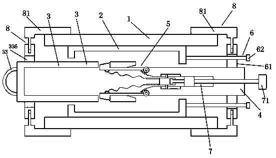
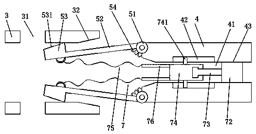
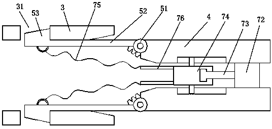
[0021] Such as Figure 1 to 5 As shown, a synchronous drive type stern tube bearing disassembly device includes a stern tube 1, a bearing 2, a pull-out ring sleeve 3, an insertion post 4, a buckle mechanism 5, a limit mechanism 6, and a synchronous clamping mechanism 8; The bearing 2 is installed inside the stern tube 1; the inner end of the plug ring sleeve 3 is inserted into the bearing 2 from one end of the bearing 2; the inner end of the plug pin 4 is inserted into the bearing 2 from the other end of the bearing 2 Inside; the upper and lower sides of the inner end of the pull ring sleeve 3 are respectively provided with a buckle groove 31; the buckle mechanism 5 includes a buckle block 53, a buckle lever 52, a rotating shaft 51, an elastic body 54; A rotating shaft 51 is installed on the upper and lower sides of the inner end of the plug-in column 4; a buckle rod 52 is rotatably installed on the rotating shaft 51; the upper and lower sides of the inner end of the plug-in column 4 are respectively Install an elastic body 54; one end of the elastic body 54 is installed on the inner end of the plug-in column 4, and the other end is connected to the buckle rod 52; one end of the buckle rod 52 is rotatably connected to the rotating shaft 51, The outer side of the other end is respectively installed with a buckle block 53; when the inner end of the plug-in column 4 is inserted into the inside of the bearing 2, the buckle block 53 is driven to move against the inner surface of the inner end of the pulling ring sleeve 3, and the buckle block 53 is clamped In the buckle groove 31 of the pulling ring sleeve 3; the limiting mechanism 6 includes a connecting ring 61 and a limiting screw 62; a connecting ring 61 is installed around the outer end of the plug column 4; the connecting The upper and lower sides of the ring 61 are respectively provided with a threaded hole; a limiting screw 62 is screwed into the threaded hole respectively; the limiting screw 62 rotates and abuts against the other end surface of the bearing 2 on the upper and lower sides. Without the action of external force, the elastic body 54 elastically connects the buckle rod 52 and makes the buckle rod 52 and the plug-in column 4 maintain an axial parallel connection, such as image 3 As shown, the buckle rod 52 and the plug post 4 are in a state where only the elastic body 54 is elastically connected. There are end rings 336 around the outer end of the pull-out ring sleeve 3; there are two synchronous clamping mechanisms 8, and both the end ring 336 and the connecting ring 61 are equipped with one synchronous Clamping mechanism 8; the synchronous clamping mechanism 8 includes a guide cylinder 82, a guide rod 83, an arc-shaped clamping plate 81, a positioning rod 85, an adjusting column 86, a drive screw 84; the end ring 336 and A guide tube 82 is installed on the upper and lower sides of the connecting ring 61; a guide rod 83 is slidably inserted into the guide tube 82; the outer end of the guide rod 83 is connected to an arc-shaped clamping plate 81; The arc-shaped clamping plate 81 is clamped and pressed against the outer surface of the stern tube 1; the rear inner end of the arc-shaped clamping plate 81 is respectively installed with a drive screw 84; the end ring 336 A positioning rod 85 is respectively installed on the middle and rear side of the connecting ring 61; the ends of the positioning rod 85 are respectively rotatably clamped to an adjusting column 86; the side of the adjusting rod 86 is rotatably clamped to the end of the positioning rod 85 , The upper and lower ends of the adjusting column 86 are provided with threaded driving grooves; the threaded driving grooves are threaded to connect the driving screw 84 at the inner end of the rear side of the arc-shaped clamping plate 81; the rotation of the adjusting column 86 drives the up and down The drive screw 84 and the arc clamping plate 81 at both ends move relatively. In the present invention, a ring-shaped clamping groove can be arranged on the side of the adjusting column, and an arc-shaped clamping block is arranged at the end of the positioning rod 85, so that the clamping groove of the adjusting column is rotatably clamped on the arc-shaped clamping block.
[0022] Such as Figure 1 to 5 As shown, it is further preferred that the axial length of the buckle groove 31 is greater than the axial length of the buckle block 53, where the axial direction refers to the axial direction of the entire bearing 2, which can facilitate the buckle block 53 to buckle. In the buckle groove 31, and leave space for the detachment of the buckle block 53 from the buckle groove 31. Further, it also includes a lever-retracting mechanism 7; the lever-retracting mechanism 7 includes a wire drawing 75, a sliding block 74, a clamping rod 73, a driving stud 72, and a driving rod 71; the inner middle of the inner end of the plug-in column 4 There is a drive 41 cavity; the upper and lower sides of the outside of the drive cavity 41 are respectively provided with sliding grooves 42; the inner circumference of the drive 41 cavity is provided with a threaded ring 43; the drive stud 72 is screwed and connected On the threaded ring surface 43 of the driving cavity 41; one end of the clamping rod 73 is fixed to one end of the driving stud 72, and the other end of the clamping rod 73 rotates to clamp the sliding block 74; the upper and lower sides of the sliding block 74 They are slidably connected to the sliding groove 42 by sliding teeth 741; one end of the sliding block 74 is connected to a drawing wire 75 on the upper and lower sides respectively; one end of the drawing wire 75 is connected to the sliding block 74, and the other end is connected to the buckle The inner side of the block 53; the other end of the driving stud 72 is equipped with a driving rod 71; one end of the driving rod 71 is fixed to the other end of the driving stud 72, and the other end of the driving rod extends to the outside of the outer end of the plug column 4. Furthermore, one end of the sliding block 74 is provided with a connecting plate 76 on the upper and lower sides respectively; one end of the drawing 75 is connected to the connecting plate 76. Furthermore, the outer side of the buckle block 53 is provided with an abutting inclined surface 531; the inner side of one end of the pulling ring sleeve 3 is provided with a tapered abutting ring 32. Further, a pull ring 33 is installed at the outer end of the pull ring sleeve 3 respectively.
[0023] The present invention adds a synchronous clamping mechanism 8, through the adjustment column 86 at one end of the positioning rod 85 for clamping rotation, so that the rotation of the adjustment column 86 drives the upper and lower ends of the drive screw 84 to expand and contract, so that the drive screw 84 drives the arc clamp The holding plate 81 performs synchronous relative movement to adjust the clamping distance of the two arc-shaped holding plates 81, so as to adapt to stern tubes of different pipe diameters; the present invention designs a cleverly structured stern shaft bearing disassembly structure. 4 When the inner end is inserted into the bearing 2, the buckle rod 52 and the buckle block 53 are driven to move to the inside of the inner end of the pull ring sleeve 3. The buckle block 52 is first pressed by the inner end surface of the pull ring sleeve 3 to make the The buckle block 53 and the buckle rod 52 rotate inwardly around the rotating shaft 51, and then the buckle block 53 and the buckle rod 52 continue to move to the inside of the pull-out ring sleeve 3, when the snap-in block 53 reaches the pull-out ring sleeve 3 When the buckle groove 31 is formed, the buckle block 53 is pressed into the buckle groove 31 by the elastic pressing of the elastic body 54, so that the pull-out ring sleeve 3 and the plug-in column 4 are locked inside the bearing 2, and then the limit The position screw 61 rotates and abuts on the upper and lower sides of the other end surface of the bearing 2. At this time, the pulling ring sleeve 3 is directly pulled out, and the bearing 2 and the plug post 4 can be pulled out directly. The structure of the present invention is cleverly designed and used convenient. The present invention adds a rod retracting mechanism 7, which is a structure for disassembling the pulling ring sleeve 3 and the plug-in column 4 after the bearing 2 is removed. By rotating the driving rod 71, the driving rod 71 drives the driving screw The column 72 rotates. When the driving stud 72 rotates and moves, the sliding block 74 is driven to move in the driving cavity 41 by the clamping rod 73, so that the sliding block 74 pulls the drawing wire 75, and the drawing 75 removes the locking block 53 from the locking groove 31 is rotated and pulled out, so that the pull ring sleeve 3 and the plug post 4 are separated.
[0024] The above descriptions are only preferred embodiments of the present invention and are not intended to limit the present invention. Any modification, equivalent replacement, improvement, etc. made within the spirit and principle of the present invention shall be included in the present invention. Within the scope of protection.

PUM

no PUM

Description & Claims & Application Information

We can also present the details of the Description, Claims and Application information to help users get a comprehensive understanding of the technical details of the patent, such as background art, summary of invention, brief description of drawings, description of embodiments, and other original content. On the other hand, users can also determine the specific scope of protection of the technology through the list of claims; as well as understand the changes in the life cycle of the technology with the presentation of the patent timeline. Login to view more.

Similar technology patents

Building construction wall cleaning device

Owner:华新建工集团有限公司 +1

Mechanical processing waste chip treatment device

Owner:TIANJIN UNIV OF TECH & EDUCATION TEACHER DEV CENT OF CHINA VOCATIONAL TRAINING & GUIDANCE

Classification and recommendation of technical efficacy words

  • Ingenious structural design
  • Ingenious structure

Automatically continuous carbon fiber winding device

ActiveCN104261202AContinuous winding and roll changingIngenious structural designFilament handlingAutomatic controlElectric machinery
Owner:ZHEJIANG JINGGONG SCI & TECH

Full-automatic assembly machine for bottom shell component of hanging headphone

ActiveCN107770715AReduce collection and transportation costsIngenious structural designMicrophonesLoudspeakersLight barrierHeadphones
Owner:CHONGQING TECH & BUSINESS UNIV

Light source capable of supplying polychromatic light and method thereof

ActiveCN101592308AEliminate spoke flareIngenious structureElectric lightingPicture reproducersSpokeLight beam
Owner:APPOTRONICS CORP LTD
Why Eureka
Try Eureka