Auxiliary device for ensuring safe demolding of mold stripping of concrete product

A technology for concrete products and auxiliary devices, applied in unloading devices, manufacturing tools, etc., can solve the problems of low work efficiency, cracking and crushing, affecting the structural strength of concrete products, etc., and achieve the effect of easy removal

Active Publication Date:
View PDF5 Cites 13 Cited by
  • Summary
  • Abstract
  • Description
  • Claims
  • Application Information

AI Technical Summary

Problems solved by technology

[0005] The purpose of the present invention is to provide an auxiliary device for concrete product mold demoulding that ensures safe demoulding, to solve the problem that the current concrete product demoulding proposed in the above background technology is generally carried out manually, mostly using rods with smaller diameters Shaped objects gradually pry the gap between the concrete product and the inner wall of the mold, so that the gap expands, so that the concrete product is disconnected from the inner wall of the mold to complete the demoulding operation, but this kind of demoulding method will cause the edge of the concrete product to pry. The cracking and crushing will affect the overall structural strength of the finished concrete product, which is not conducive to stable use in the later stage, and affects the safety of the relevant structure of the main building. The traditional demoulding method is relatively inefficient, and it is necessary to gradually pry the different inner walls of the mold. It is easy to damage the integrity of concrete products and also easily damage the structure of the mold itself, which is not conducive to the long-term use of the mold and increases the loss rate of the mold

Method used


Image

  • Auxiliary device for ensuring safe demolding of mold stripping of concrete product
  • Auxiliary device for ensuring safe demolding of mold stripping of concrete product
  • Auxiliary device for ensuring safe demolding of mold stripping of concrete product

Examples


Embodiment Construction

[0025] The following will clearly and completely describe the technical solutions in the embodiments of the present invention with reference to the accompanying drawings in the embodiments of the present invention. Obviously, the described embodiments are only some, not all, embodiments of the present invention. Based on the embodiments of the present invention, all other embodiments obtained by persons of ordinary skill in the art without making creative efforts belong to the protection scope of the present invention.

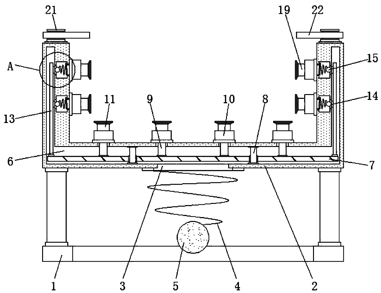
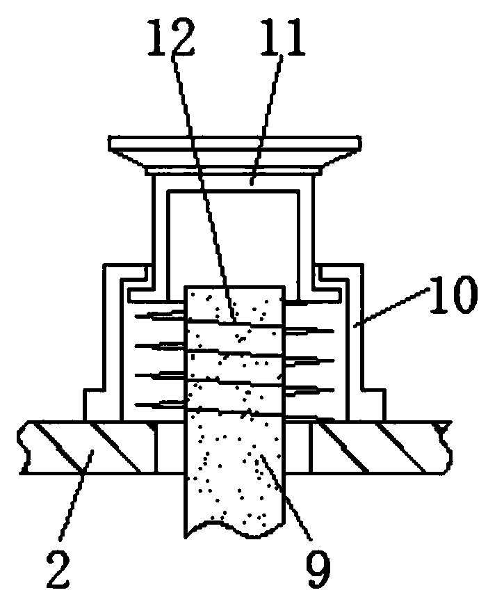
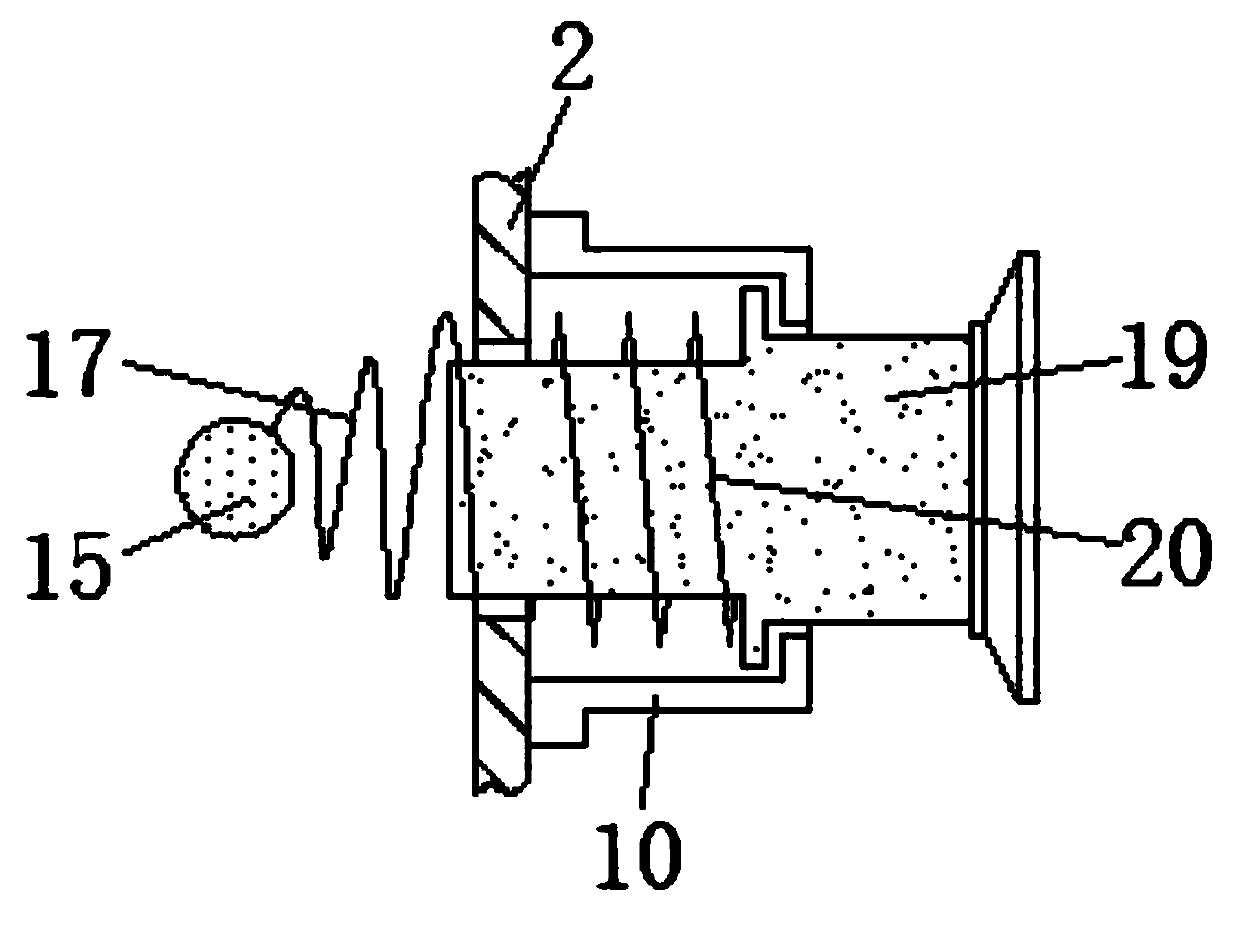
[0026] see Figure 1-6 , the present invention provides a technical solution: an auxiliary device for demoulding a concrete product mold that ensures safe demoulding, including a support frame 1, a first return spring 12, a second return spring 20 and a vertical shaft 21, the support frame 1 is installed with a placement basket 2, and the bottom of the placement basket 2 is provided with an opening 3, and the bottom of the placement basket 2 is equipped with a...


PUM


Abstract

The invention discloses an auxiliary device for ensuring safe demolding of mold stripping of a concrete product. The auxiliary device comprises a bearing frame, first reset springs, second reset springs and vertical shafts. A containing basket is mounted above the bearing frame. An opening is formed in the bottom of the containing basket. A first conical spring is mounted below the containing basket and located at the outer side of the opening. The vertical shafts are mounted at the upper end of the containing basket. Baffles are mounted on the vertical shafts. The baffles are connected with the containing basket through the vertical shafts. According to the auxiliary device for ensuring safe demolding of mold stripping of the concrete product, a mold filled with the concrete product is conveniently placed on the inner side of the containing basket, and first ejector rods and second ejector rods extend out of mounting sleeves and are in fit contact with the outer surface of the mold correspondingly under the pushing of the first reset springs and the second reset springs, so that the mold can be conveniently and stably placed, subsequent knocking vibration on the side wall of the mold is facilitated, and the demolding operation is finally completed.

Description

technical field [0001] The invention relates to the technical field of demoulding of concrete products, in particular to an auxiliary device for demoulding a concrete product mold to ensure safe demoulding. Background technique [0002] In the construction industry, one of the most used building materials is concrete. Concrete and steel bars are usually used as the main structure of the building. In the process of engineering construction, concrete is also prefabricated into different shapes of concrete prefabricated components through molds. Such components are generally manufactured in advance. When they need to be used, the completed concrete prefabricated components only need to be taken out of the mold and assembled to obtain the required structure. Therefore, in this process, the concrete products are usually involved. The operation of complete removal from the mold, but the existing removal operation usually has the following problems: [0003] 1. The current demould...

Claims


Application Information

Patent Timeline
Patent Type & Authority Applications(China)
IPC IPC(8): B28B13/06
CPCB28B13/067
Inventor 李洋
Why Eureka
Try Eureka