Eureka AIR delivers breakthrough ideas for toughest innovation challenges, trusted by R&D personnel around the world.

Plastic plate continuous bending device

A technology of bending device and plastic plate, which is applied in the field of plastic bending machine, can solve the problems of bending device failure, continuous bending, long production cycle, etc., and achieve the effect of precise angle, small air knife opening and cost saving

Pending Publication Date: 2020-02-21
新乡市仲达塑胶电子有限公司
View PDF0 Cites 5 Cited by
  • Summary
  • Abstract
  • Description
  • Claims
  • Application Information

AI Technical Summary

Problems solved by technology

[0003] In view of the above situation, in order to overcome the defects of the prior art, the present invention provides a continuous bending device for plastic plates, which solves the problems that the existing bending device cannot perform continuous bending and has a long production cycle

Method used


Image

  • Plastic plate continuous bending device
  • Plastic plate continuous bending device
  • Plastic plate continuous bending device

Examples


Embodiment 1

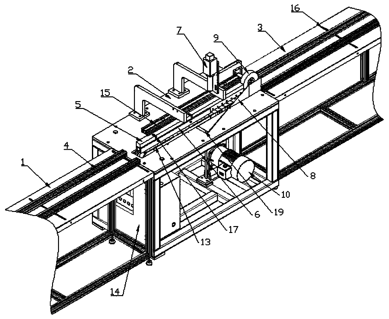
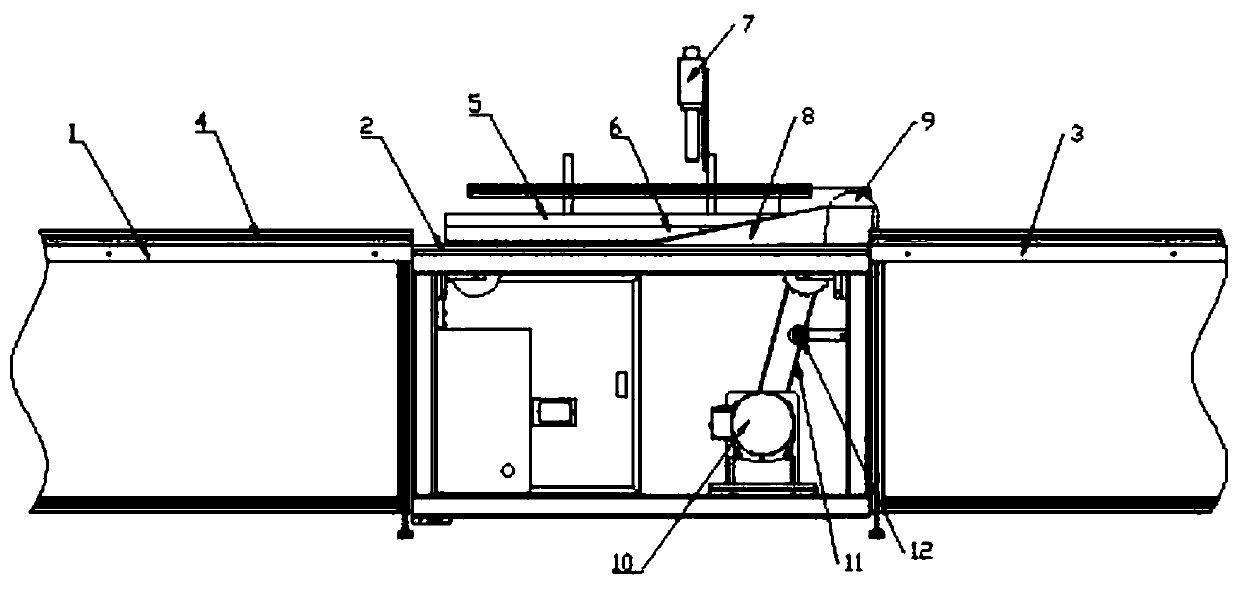
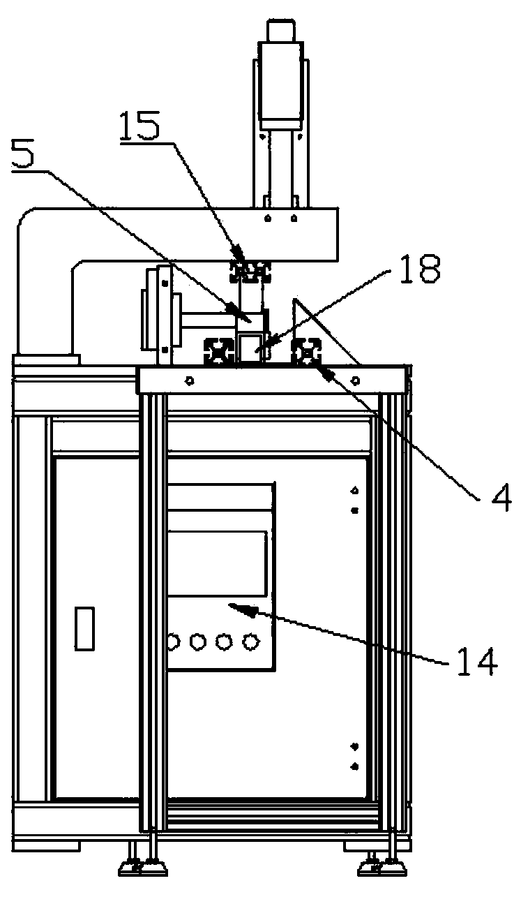
[0022] Embodiment one: by Figure 1 to Figure 4 Given, the plastic sheet continuous bending device includes bending device 2, feeding platform 1 and shaping platform 3, the plastic sheet is fed from feeding platform 1 to the bending device, and after being bent by the bending device, it is The material is discharged at the platform 3 and is shaped during the discharging process. The bending device 2 is located between the feeding platform 1 and the shaping platform 3, and a shaping transmission wheel 9 is arranged between the bending device 2 and the shaping platform to avoid The plastic plate is deformed, and the bending device includes a chain slat 13, a conveying pressure wheel 5, a heating device and a bending guide plate 8, and the chain slat 13 is made of steel to prevent the heating device from heating the plastic plate. The chain slats are heated and deformed. The chain slats 13 are driven by the transmission motor 10 through the belt 11 to drive the tension wheel 12 t...

Embodiment 2

[0023] Embodiment 2: In one embodiment, the transmission pressure roller 5 includes an upper force application block and a lower transmission block, and the transmission block is provided with a hollow groove with an opening facing downwards on the side facing the chain slats 13 , and the hollow groove A plurality of transmission wheels 18 are arranged in the groove, and the described force block is a solid metal block, which is used to increase the quality of the transmission pressure roller 5, and compresses the plastic plate to prevent it from warping or shifting. The lower part is changed from sliding friction to rolling friction, which facilitates the transmission of the plastic plate. The force applying block and the transmission block are integrally made, and a pressure bar 15 for adjusting the height of the transmission pressure wheel 5 is arranged above the transmission pressure wheel 5. Bolts are set between the rod 15 and the delivery pinch roller 5, and the bolts ar...


PUM

PropertyMeasurementUnit
Widthaaaaaaaaaa

Abstract

The invention relates to the technical field of plastic bending machines, in particular to a plastic plate continuous bending device. An existing bending device cannot perform continuous bending and is long in production cycle. The plastic plate continuous bending device comprises a bending device, a feeding platform and a shaping platform. The bending device is located between the feeding platform and the shaping platform. The bending device comprises a chain batten, a conveying pressing wheel, a heating device and a bending and guiding plate. The chain batten drives a tensioning wheel to rotate through a belt by means of a transmission motor so as to provide power. The bending and guiding plate is a rectangular thin plate. One end of the bending and guiding plate is attached to the surface of an operation platform, and the other end of the bending and guiding plate is perpendicular to the operation platform to form an arc-shaped plate with gradient. A limiting device is arranged on the feeding platform and the shaping platform. Continuous bending is realized, bending and shaping can be performed at the same time but different stages, the production cycle is shortened, and the plastic plate continuous bending device has broad development prospects in the technical field of plastic bending machines.

Description

technical field [0001] The invention relates to the technical field of plastic bending machines, in particular to a continuous bending device for plastic plates. Background technique [0002] The current implementation of the hollow plate plastic bending machine is to adopt the method of length customization. If the demand is 3 meters, it will be 3 meters, and if the demand is 6 meters, it will be 6 meters. There are limitations in the production length of the equipment, which takes up a lot of space, especially in the current market. There is no equipment more than 6 meters above, and the production method adopts one-piece bending and then shaping. The bending and shaping processes are separated. The production cycle is long, continuous production is not possible, and the length is limited. Therefore, the production efficiency is low and the cost is high. Contents of the invention [0003] In view of the above situation, in order to overcome the defects of the prior art, ...

Claims


Application Information

Patent Timeline
IPC IPC(8): B29C53/04B29C53/80B29C53/84
CPCB29C53/04B29C53/80B29C53/84
Inventor 张艳宾乔志宏赵世友张轩
Owner 新乡市仲达塑胶电子有限公司
Why Eureka
Eureka Blog
Learn More