Anti-dandruff shampoo and preparation system and processing method thereof

A preparation system, shampoo technology, applied in the direction of manufacturing tools, pharmaceutical formula, hair care, etc., can solve the problems of not being able to beat the raw materials to produce juice, extract the original solution, etc.

Active Publication Date: 2020-02-21
佛山市百分之秀化妆品有限公司
View PDF9 Cites 4 Cited by
  • Summary
  • Abstract
  • Description
  • Claims
  • Application Information

AI Technical Summary

Problems solved by technology

But this utility model can not fully beat the raw material to extract the juice

Method used


Image

  • Anti-dandruff shampoo and preparation system and processing method thereof
  • Anti-dandruff shampoo and preparation system and processing method thereof
  • Anti-dandruff shampoo and preparation system and processing method thereof

Examples


specific Embodiment approach 1

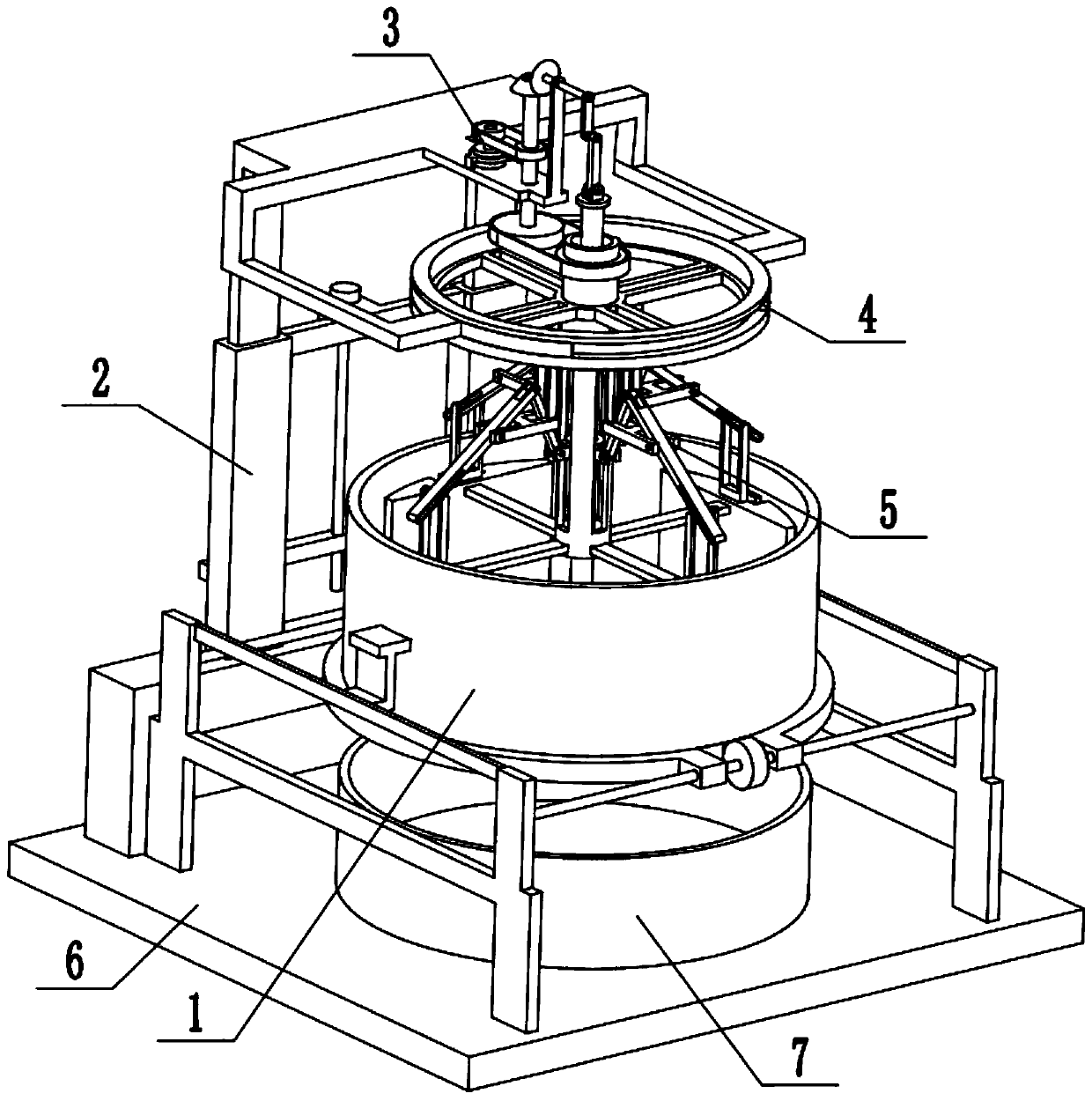
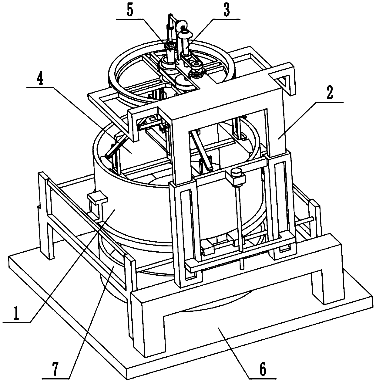
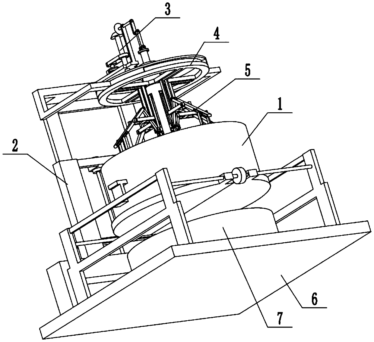
[0033] Combine below Figure 1-10 Describe this embodiment, a preparation system for anti-dandruff shampoo, including a material extrusion cylinder assembly 1, a lifting adjustment mechanism 2, a material rotating extrusion mechanism 3, a power output mechanism 4, an extrusion driving mechanism 5, a base 6 and a material A collection box 7, the material extrusion cylinder assembly 1 is fixedly connected to the base 6, the material collection box 7 is placed on the base 6, the material collection box 7 is located below the material extrusion cylinder assembly 1, and the lifting adjustment mechanism 2 is fixedly connected to Behind the material extrusion cylinder assembly 1, the material rotary extrusion mechanism 3 is arranged on the upper end of the lifting adjustment mechanism 2, the upper end of the power output mechanism 4 is arranged on the lifting adjustment mechanism 2, and the lower end of the power output mechanism 4 is located on the material extrusion cylinder assembl...

specific Embodiment approach 2

[0035] Combine below Figure 1-10 To illustrate this embodiment, the material extrusion cylinder assembly 1 includes a side frame 1-1, a guide rod 1-2, a bidirectional screw 1-3, a bottom plate 1-4, a screw ring 1-5, and a circular cylinder 1 -6 and the fixed frame 1-7; the guide rod 1-2 is fixedly connected to the rear end of the two side frames 1-1, and the two-way screw rod 1-3 is rotated and connected to the front ends of the two side frames 1-1. The rear ends of the two bottom plates 1-4 are symmetrically slidably connected to the guide rod 1-2, and the front ends of the two bottom plates 1-4 are connected to the two ends of the two-way screw rod 1-3 through thread fit, and the screw ring 1-5 is fixedly connected. In the middle of the two-way screw 1-3, the two ends of the circular tube 1-6 are respectively fixedly connected to a fixed frame 1-7, and the two fixed frames 1-7 are respectively fixedly connected to the two side frames 1-1, and the circular The bottom surfac...

specific Embodiment approach 3

[0037] Combine below Figure 1-10 To illustrate this embodiment, the lift adjustment mechanism 2 includes a portal frame 2-1, a rectangular hollow column 2-2, a rectangular through slot 2-3, a slide bar 2-4, a U-shaped plate 2-5, and a drive motor I2 -6, lead screw 2-7, top frame plate 2-8, shift fork 2-9, horizontal shaft frame plate 2-10 and vertical shaft frame plate 2-11; portal frame 2-1 is fixedly connected to base 6 On the top, two rectangular hollow columns 2-2 are fixedly connected to the portal frame 2-1, and the rear ends of the two rectangular hollow columns 2-2 are respectively provided with a rectangular through groove 2-3, and the two ends of the U-shaped plate 2-5 The two ends of the U-shaped plate 2-5 are respectively fixedly connected to a sliding rod 2-4, and the two sliding rods 2-4 are respectively slidingly fitted and connected to the two rectangular hollow slots. In the column 2-2, the driving motor I2-6 is fixedly connected between two rectangular holl...


PUM


Abstract

The invention discloses anti-dandruff shampoo and a preparation system and processing method thereof. The shampoo comprises the components of 10 parts of coix seed extract, 2 parts of camellia extract, 5 parts of cinnamon extract, 3 parts of ginseng extract, 1 part of red peony root extract, 2.5 parts of coconut diethanolamide, 0.5 part of astragalus extract, 0.5 part of kelp extract, 10 parts ofglycerin, 8 parts of conditioners, 0.1 part of essence, 0.1 part of preservative and 25 parts of deionized water. The processing method comprises the steps that 1, raw materials obtained after soakingare put into a material extrusion barrel assembly; 2, the raw materials in the material extrusion barrel assembly are hit by a round pressing disc, and meanwhile four extrusion plates constantly pushand gather pressed-scattered raw materials to be below the round pressing disc; 3, the four rotating extrusion plates push all the raw materials to be below the round pressing disc to be hit; 4, a material rotary extrusion mechanism and an extrusion driving mechanism move upwards; and 5, the raw materials in a material collection box and other components are stirred so as to be mixed evenly.

Description

technical field [0001] The invention relates to the technical field of shampoo production and processing, in particular to an anti-dandruff shampoo and its preparation system and processing method. Background technique [0002] The patent number is CN201520723570.3 for a portable plant essence extraction device. The utility model relates to a portable plant essence extraction device, which includes an electric distillation device shell and a cooling device fixed on one side of the electric distillation device shell. The shell, the electric distillation device installed in the shell of the electric distillation device, and the cooling device fixedly installed in the shell of the cooling device; the electric distillation device includes a distillation pot body, a heating pipe and a sealing cover; the bottom of the distillation pot body is in contact with the heating pipe; the cooling device Including the heat dissipation fin coil and fan fixedly arranged in the upper middle pa...

Claims


Application Information

Patent Timeline
Patent Type & Authority Applications(China)
IPC IPC(8): B30B9/04B30B15/04B30B15/32A61K8/9706A61K8/9789A61K8/9794A61Q5/00A61Q5/02
CPCA61Q5/006A61Q5/02A61K8/9706A61K8/9789A61K8/9794B30B9/04B30B15/04B30B15/32
Inventor 高林生
Owner 佛山市百分之秀化妆品有限公司
Why Eureka
Try Eureka