Box sealing mechanism convenient to operate

A technology of sealing and moving mechanism, applied in packaging and other directions, can solve the problems of easy to slightly shake or tilt, not suitable for large-scale import promotion, and high manufacturing cost of packaging machines, so as to achieve easy promotion and use, simple structure, and improved service life. Effect

Pending Publication Date: 2020-02-21
合肥哈工龙延智能装备有限公司
0 Cites 0 Cited by

AI-Extracted Technical Summary

Problems solved by technology

[0002] Carton packaging machinery is developed with the development of related science and technology and modern logistics industry. It integrates machinery, electricity and gas. It is a machine that packs inner-packaged goods into boxes during the production process. One of the keys, with the rapid increase in the demand for commodity packaging with the development of the express industry, and the shortage of labor force brought about by the aging society, the automation of commodity packaging operations has become the only way for the development of the current express industry. The manufacturing cost of foreign packaging machines is high, far from It exceeds the purchasing power of Chinese farmers and is not ...

Abstract

The invention relates to a box sealing mechanism convenient to operate. The box sealing mechanism convenient to operate comprises a box sealing support. The box sealing support comprises two conveyingside frames. An auxiliary roller plate is arranged between the two conveying side frames, and guide wheels are arranged above the auxiliary roller plate. An upper box sealing device is arranged abovethe auxiliary roller plate, and a lower box sealing device is arranged in the middle of the auxiliary roller plate. The box sealing support comprises a fixing side plate. A telescopic moving mechanism is connected with the outer surface of the fixing side plate, an upper support is fixedly connected with the moving end of the telescopic moving mechanism, and the upper box sealing device is connected with the upper support. The upper support comprises a moving side frame. The telescopic moving mechanism comprises a first side column and a second side column. The box sealing mechanism convenient to operate is convenient to use and easy to operate, the height of the upper support is conveniently adjusted, and the stability of the upper support in the moving process is effectively improved. In addition, the box sealing mechanism convenient to operate is simple in structure, low in manufacturing cost and convenient to popularize and use.

Application Domain

Packaging

Technology Topic

Structural engineeringManufacturing engineering +1

Image

  • Box sealing mechanism convenient to operate
  • Box sealing mechanism convenient to operate
  • Box sealing mechanism convenient to operate

Examples

  • Experimental program(2)

Example Embodiment

[0017] Example 1
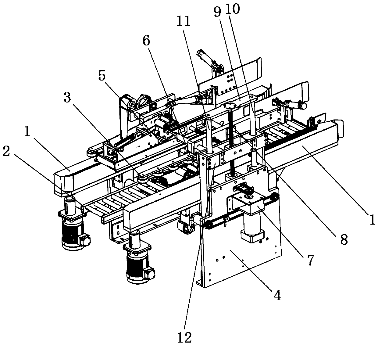
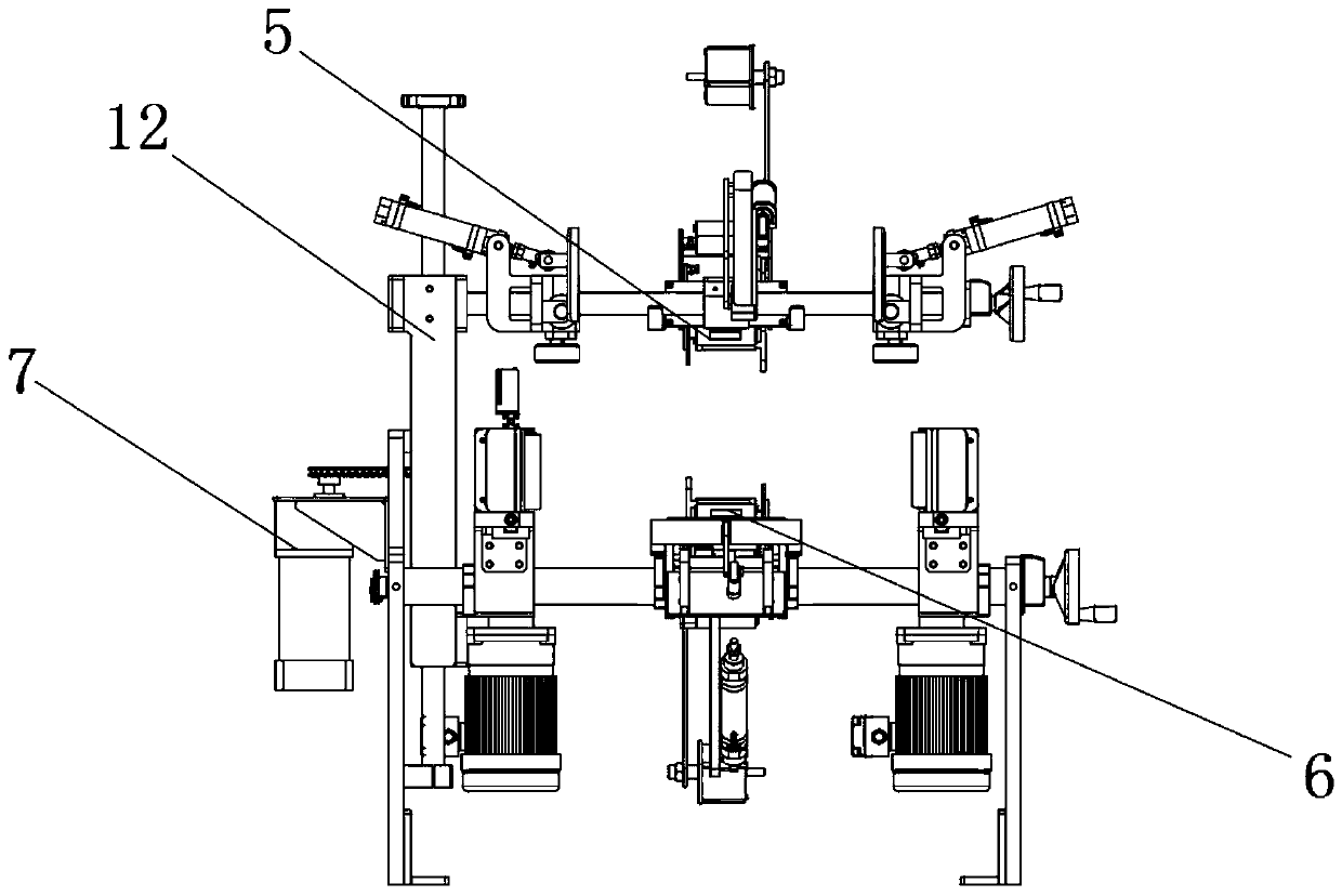
[0018] Such as Figure 1-2 As shown, an easy-to-operate box sealing mechanism includes a box sealing bracket. The box sealing bracket includes two sets of conveying side frames 1. An auxiliary roller plate 2 is provided between the two sets of conveying side frames 1. A guide wheel 3 is provided above the roller plate 2, an upper box sealer 5 is provided above the auxiliary roller plate 2, a lower box sealer 6 is provided in the middle of the auxiliary roller plate 2, and the box sealing bracket includes The fixed side plate 4, the outer surface of the fixed side plate 4 is connected with a telescopic moving mechanism, the moving end of the telescopic moving mechanism is fixedly connected with an upper bracket, and the upper box sealer 5 is connected with the upper bracket. Generally speaking, The inner surface of the conveying side frame 1 is provided with a conveyor belt, and the side wall of the box body is clamped by the conveying side frame 1 to convey the box body. The upper box sealer 5 and the lower box sealer 6 are both commonly used box sealers. The upper end surface and the lower end surface of the body are sealed, and the telescopic moving mechanism can also adopt other telescopic moving mechanisms. In this embodiment, the following structure is adopted.
[0019] The upper bracket includes a moving side frame 12, the telescopic moving mechanism includes a No. 1 side post 10 and a No. 2 side post 11, and the outer surface of the upper end of the No. 1 side post 10 and the No. 2 side post 11 is connected with a fixed top plate 9 The first side post 10 and the second side post 11 both penetrate the moving side frame 12, and the moving side frame 12 moves up and down along the first side post 10 and the second side post 11; the telescopic moving mechanism includes a drive motor , The rotating end of the driving motor is connected with a screw 8, the outer surface of the upper end of the screw 8 is movably connected with the fixed top plate 9, the screw 8 can rotate relative to the fixed top plate 9, and the outer surface of the screw 8 is connected to the movable side frame 12 Threaded connection, through the drive motor to drive the screw 8 to rotate, prompting the mobile side frame 12 to move up and down along the side post 10, so as to adjust the position of the upper box sealer 5; to make the movement of the mobile side frame 12 more stable, make the following settings: The outer surface of the fixed side plate 4 is fixedly connected with a motor support 7 and the drive motor is located in the motor support 7; the outer surface of the lower end of the screw 8 is fixedly connected with a connecting gear 13, and the rotating end of the drive motor Connect with the chain of the connecting gear 13; set the motor support 7 and the drive motor on the other side of the fixed side plate 4, and use the chain drive connection at the same time, and the drive is relatively stable. The drive motor rotates the servo motor to meet the requirements of forward and reverse control. Yes, the specific model can be selected by the weight of the actual movable side frame 12, and there are no other restrictions.

Example Embodiment

[0020] Example 2
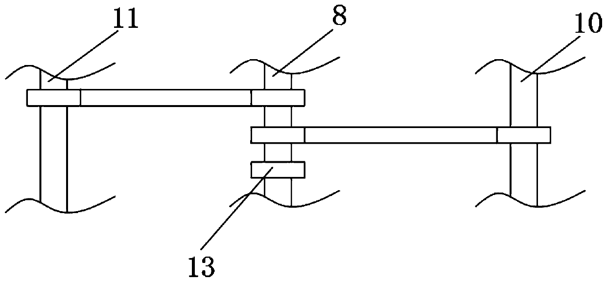
[0021] Such as image 3 As shown, on the basis of the above-mentioned embodiment 1, in order to make the moving side frame 12 connected to the upper box sealer 5 more stable in the up and down movement, the following improvements are made. The outer surface of the screw 8 and the first side Both the column 10 and the second side column 11 are connected by a chain. In this embodiment, the outer surfaces of the first side column 10 and the second side column 11 are both provided with threaded structures, and the first side column 10 and the second side column 11 Both are threadedly connected with the movable side frame 12. Specifically, two sets of gears of the same model as the connecting gear 13 can be fixed on the surface of the screw 8 and then connected by a chain. In actual use, since the three sets of gears are of the same model, the screw 8 and The rotation speed of the No. 1 side post 10 and the No. 2 side post 11 are the same, so the upward moving force of the moving side frame 12 is provided by the No. 1 side post 10, the second side post 11 and the screw 8 together, and the moving side frame 12 and the No. 1 side post 10, and the No. 2 side post 11 and the screw 8 are all connected by threads. At this time, the stability of the entire movable side frame 12 is greatly improved.

PUM

no PUM

Description & Claims & Application Information

We can also present the details of the Description, Claims and Application information to help users get a comprehensive understanding of the technical details of the patent, such as background art, summary of invention, brief description of drawings, description of embodiments, and other original content. On the other hand, users can also determine the specific scope of protection of the technology through the list of claims; as well as understand the changes in the life cycle of the technology with the presentation of the patent timeline. Login to view more.

Similar technology patents

Electric system low-frequency oscillation mode parameter identification method

ActiveCN104242325AInhibit the occurrence of low frequency oscillationimprove stability
Owner:STATE GRID CORP OF CHINA +2

Gemcitabine hydrochloride lyophilized powder injection

ActiveCN101564381AImprove stabilityLow content of related substances
Owner:JIANGSU AOSAIKANG PHARMA CO LTD

Classification and recommendation of technical efficacy words

  • Improve stability
  • Extended service life

Fracturing manifold quick connecting device

Owner:YANTAI JEREH PETROLEUM EQUIP & TECH

Modified asphalt composition with creeping characteristic and preparation method thereof

InactiveCN102020859Aavoid rapid agingExtended service life
Owner:ZHEJIANG WOPUMAN HIGH NEW MATERIALS
Why Eureka
Try Eureka