
Sponge feeding device

A feeding device and sponge technology, which is applied in the field of auto parts, can solve the problems of difficult automation of sponge and leather bonding, low efficiency of manual bonding of sponge and leather, and troublesome manual operations.

Pending Publication Date: 2020-02-21
GUANGZHOU COLLEGE OF SOUTH CHINA UNIV OF TECH
View PDF0 Cites 1 Cited by
  • Summary
  • Abstract
  • Description
  • Claims
  • Application Information

AI Technical Summary

Problems solved by technology

[0002] At present, the sponge and leather in the automotive leather parts industry are mostly glued together for connection. However, due to the light weight of the sponge and the complex and diverse shapes of the leather parts, it is difficult to automate the bonding of the sponge and leather. Most automotive leather companies still use manual bonding methods to bond sponges and leather parts
[0003] As more and more private cars enter private homes, the demand for automotive leather parts is also increasing. The method of artificially bonding sponge and leather is inefficient and has deviations in accuracy. Obviously, the method of artificially bonding sponge and leather is no longer possible. To meet the needs of enterprises, the existing sponge feeding is generally delivered to the conveyor belt by manual feeding, but this feeding method is time-consuming, and because the sponge texture is relatively soft, it brings trouble to manual operation, thus In order to improve production efficiency, there is an urgent need for a sponge feeding device

Method used


Image

  • Sponge feeding device
  • Sponge feeding device
  • Sponge feeding device

Examples


Embodiment Construction

[0019] The present invention will be described in further detail below in conjunction with the accompanying drawings and specific embodiments.

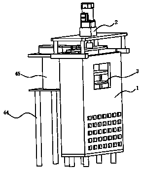
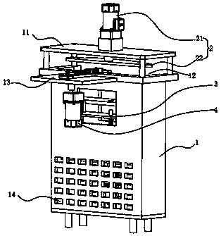
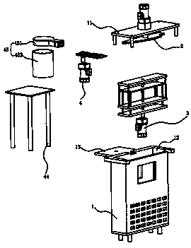
[0020] A sponge feeding device, comprising a feeding housing 1, a vibration detachment device 2, an up and down pushing device 3 and a sponge pushing device 4, the top of the feeding housing 1 is provided with a feeding fixing plate 11 and a feeding port 12, and the up and down pushing The device 3 is arranged on the feeding housing 1 on the side of the feeding port 12, the feeding fixed plate 11 is arranged above the feeding port 12, the vibration detachment device 2 is arranged above the feeding fixed plate 11, and the sponge pushing device 4 is arranged on the feeding housing 1 in front of the feeding direction.

[0021] The vibration detachment device 2 includes a detachment motor 21, the output end of the detachment motor 21 passes through the feeding fixed plate 11, and the output end of the detachment motor 21 is provided with ...


PUM


Abstract

The invention provides a sponge feeding device which comprises a feeding shell, a vibration separating device, an up-and-down pushing device and a first sponge pushing device. A feeding fixed plate and a feeding opening are arranged at the top of the feeding shell. The up-and-down pushing device is arranged on the feeding shell. The feeding fixed plate is arranged above the feeding opening. The vibration separating device is arranged above the feeding fixed plate. The sponge pushing device is arranged in front of the conveying direction of the feeding shell. The sponge feeding device has the advantages that to-be-processed sponges are automatically separated and fed.

Description

technical field [0001] The invention relates to the field of auto parts, in particular to a sponge feeding device. Background technique [0002] At present, the sponge and leather in the automotive leather parts industry are mostly glued together for connection. However, due to the light weight of the sponge and the complex and diverse shapes of the leather parts, it is difficult to automate the bonding of the sponge and leather. Most automotive leather companies still use artificial bonding methods to bond sponges and leather parts. [0003] As more and more private cars enter private homes, the demand for automotive leather parts is also increasing. The method of artificially bonding sponge and leather is inefficient and has deviations in accuracy. Obviously, the method of artificially bonding sponge and leather is no longer possible. To meet the needs of enterprises, the existing sponge feeding is generally delivered to the conveyor belt by manual feeding, but this feedi...

Claims


Application Information

Patent Timeline
IPC IPC(8): B65G47/82B65G47/88
CPCB65G47/82B65G47/88
Inventor 韩伟段海峰廖志青江丽珍刘楚生陈宇姗
Owner GUANGZHOU COLLEGE OF SOUTH CHINA UNIV OF TECH
Learn More