
Flame stabilizing structure of combustion chamber

A flame stabilization structure and flame stabilization technology are applied in the field of combustion structure device and combustion structure structure, which can solve the problems of difficulty in meeting the requirements of flow resistance and combustion efficiency, so as to enhance flame stability, reduce flow loss, and reduce airflow loss. Effect

Active Publication Date: 2020-02-21
INST OF ENGINEERING THERMOPHYSICS - CHINESE ACAD OF SCI
View PDF8 Cites 8 Cited by
  • Summary
  • Abstract
  • Description
  • Claims
  • Application Information

AI Technical Summary

Problems solved by technology

The large groove width stabilizer structure and the fuel injection and mixing structure before the stabilizer used in the traditional afterburner are difficult to meet the requirements of the new generation of afterburner for flow resistance and combustion efficiency

Method used


Image

  • Flame stabilizing structure of combustion chamber
  • Flame stabilizing structure of combustion chamber
  • Flame stabilizing structure of combustion chamber

Examples


Embodiment Construction

[0028] In order to make the object, technical solution and advantages of the present invention clearer, the present invention will be further described in detail below with reference to the accompanying drawings and examples.

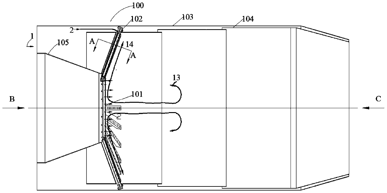
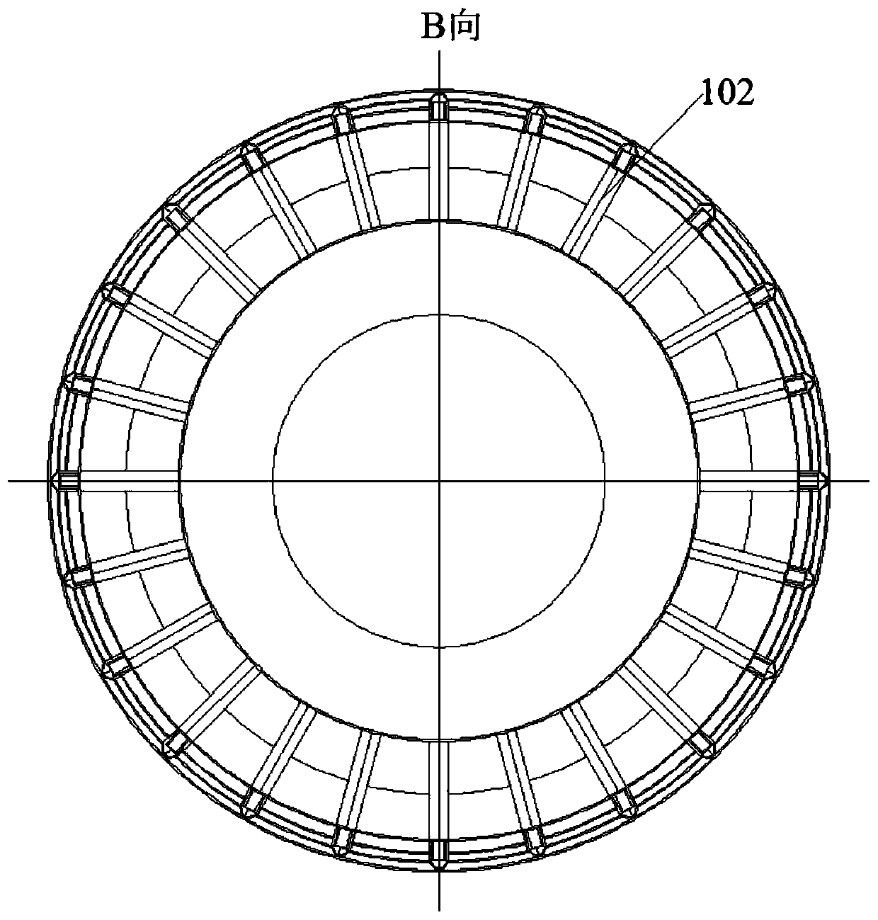
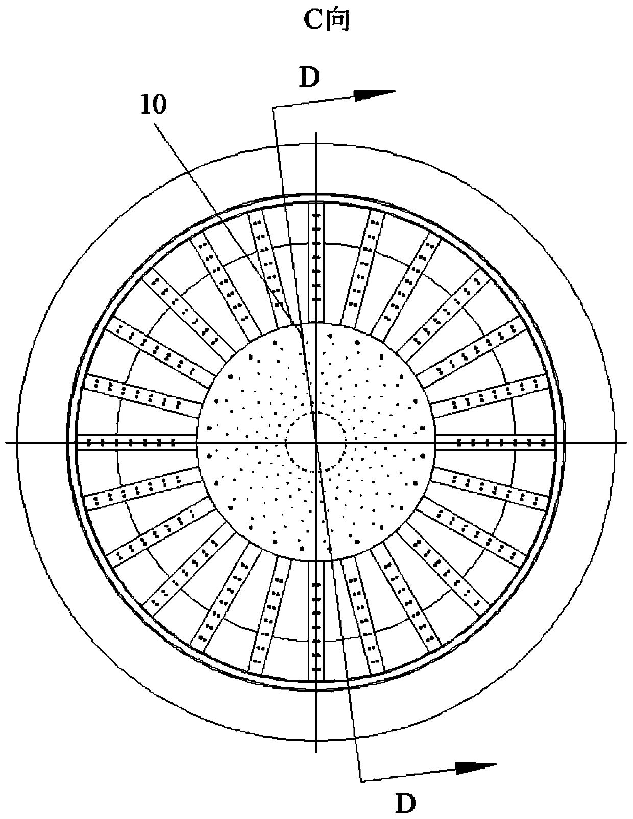
[0029] The combustion chamber flame stabilization structure with enhanced flame stability and reduced losses of the present invention can be widely used in afterburner combustion chambers of turbojet engines with wide speed range and high thrust-to-weight ratio, ramjet combustion chambers or super combustion chambers of turbine-based combined cycle engines. To enhance flame stability and reduce flow loss under high-speed incoming flow conditions. Figure 1~3Shown is the flame stabilization structure of the combustion chamber of the present invention, which is applied to the situation in the afterburner of a turbojet engine with a wide speed range and high thrust-to-weight ratio.

[0030] Such as Figure 1~3 As shown, the afterburner 100 is located behi...


PUM

PropertyMeasurementUnit
Groove widthaaaaaaaaaa
Diameteraaaaaaaaaa

Abstract

The invention relates to a flame stabilizing structure of a combustion chamber and the combustion chamber comprising the flame stabilizing structure. The flame stabilizing structure of the combustionchamber comprises a truncated cone arranged in a flame cylinder and multiple V-shaped radial flame stabilizers evenly arranged on the periphery of the truncated cone in the circumferential direction.The truncated cone and the V-shaped radial flame stabilizers are of hollow structures and are provided with oil spraying holes. The top ends of the V-shaped radial flame stabilizers lead low-temperature air into the V-shaped radial flame stabilizers and the truncated cone so as to cool the V-shaped radial flame stabilizers and the truncated cone. By means of the arrangement of the above structures, a low-speed flow return area formed by the large-size truncated cone is used for improving the flame stability, the small-groove-with V-shaped radial flame stabilizers are used for spreading flamesand reducing airflow losses, the stabilizing function and the spreading function of flames are separated, and due to integrated design of a fuel injection device and the stabilizers, flowing losses can be further reduced. The flame stabilizing structure can be widely applied to high-speed-area and high-thrust-weight-ratio turbojet engine stress application combustion chambers, ramjet combustion chambers and turbine based combined cycle engine super combustion chambers.

Description

technical field [0001] The invention relates to the field of combustion of power plants, and relates to a flame stabilization structure of a combustion chamber, which is a combustion structure device that enhances flame stability and reduces flow loss, and specifically relates to a turbine that is applied in a wide speed range and high thrust-to-weight ratio Combustion organization of jet engine afterburner. Background technique [0002] Under high flow conditions, special devices must be used in the combustion chamber to stabilize the flame. The key to flame stabilizer design is to construct a low velocity flow region to ignite the combustible mixture. In the main combustion chamber of a turbojet engine, the airflow velocity is 30-60 m / s, and a swirl structure is usually used to stabilize the flame. In the afterburner, the airflow velocity is as high as 120-180 m / s, which is much higher than that in the main combustion chamber , Usually a diffuser is used to slow down, an...

Claims


Application Information

Patent Timeline
IPC IPC(8): F23R3/20
CPCF23R3/20
Inventor 邓爱明赵庆军胡斌赵巍项效镕周小勇
Owner INST OF ENGINEERING THERMOPHYSICS - CHINESE ACAD OF SCI
Learn More