Multi-stage oil-gas separator

A technology of oil and gas separator and separation cylinder, which is used in refrigeration components, refrigerators, lighting and heating equipment, etc., can solve the problems of poor separation effect and large exhaust adjustment range of compressors, and achieve the effect of high oil and gas separation effect.

Inactive Publication Date: 2020-02-21
广东捷邦节能设备制造有限公司
View PDF4 Cites 4 Cited by
  • Summary
  • Abstract
  • Description
  • Claims
  • Application Information

AI Technical Summary

Problems solved by technology

[0004] However, the above-mentioned oil separator has the following disadvantages: when the flow rate of the gaseous refrigerant is large, the flow rate entering the cylinder is high, and the centrifugal force on the oil droplets in the refrigerant is large. At the same time, if the flow rate exceeds a certain range, it will cause accumulation on the surface of the cylinder The oil droplets are re-entangled into the gaseous refrigerant, so the flow rate of the gaseous refrigerant has an optimal separation range; when the flow rate of the gaseous refrigerant is small, the flow rate into the cylinder is low, and the centripetal force on the oil droplets in the refrigerant is small, so Its separation effect is poor
Especially in the frequency conversion system, the adjustment range of the compressor exhaust is large, and the above oil separator can only meet the high separation efficiency within a certain range.

Method used


Image

  • Multi-stage oil-gas separator
  • Multi-stage oil-gas separator

Examples


Embodiment Construction

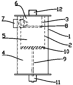
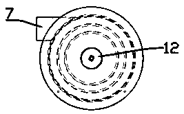
[0016] The technical solution of the present invention will be further described in conjunction with the accompanying drawings.

[0017] Such as figure 1 , 2 As shown, the present invention includes an outer cylinder 1 , an intermediate separation cylinder 2 and an inner cylinder 3 . Wherein, the outer cylinder 1 is a hollow structure with a first cavity 4 inside. The middle separation cylinder 2 is a hollow structure with a second cavity 5 inside. The inner cylinder 3 has a third cavity 6 inside. The intermediate separation cylinder 2 is disposed in the first cavity 4, specifically on the lower surface of the top of the outer cylinder 1, and the inner cylinder 3 is disposed in the second cavity 5, specifically on the lower surface of the top of the intermediate separation cylinder 2. On the surface, it can be understood that the inner cylinder 3 is also arranged on the lower surface of the top of the outer cylinder 1 . The air inlet pipe 7 communicates with the first cav...


PUM


Abstract

The invention discloses a multi-stage oil-gas separator. The oil-gas separator comprises an outer cylinder body, an intermediate separation cylinder, an inner cylinder body, a gas inlet pipe, an exhaust pipe and an oil guide pipe; a first filter screen is arranged at the inner bottom of the inner cylinder body, the intermediate separation cylinder is arranged in a first cavity, and the inner cylinder body is arranged in a second cavity; and the gas inlet pipe is in communication with the first cavity of the outer cylinder body through a first opening formed in the upper portion of the side part of the outer cylinder body, the exhaust pipe is in communication with a third cavity of the inner cylinder body through a second opening formed in the top of the outer cylinder body, and the oil guide pipe is in communication with the second cavity of the intermediate separation cylinder through a third opening formed in the bottom of the intermediate separation cylinder. The oil-gas separator realizes the effect that the centrifugal separation effect is changed due to the change of the discharge amount in the variable load regulation process of a refrigerating unit, but the good separationeffect can be obtained under different flow rates.

Description

technical field [0001] The invention relates to a multistage oil-gas separator used in a refrigeration system, and in particular provides a multistage centrifugal and filter screen compound separation oil separator which satisfies high separation efficiency when the flow rate changes. Background technique [0002] Generally speaking, the oil separator in the refrigeration system is set between the exhaust port of the compressor and the condenser, which is used to separate the lubricating oil in the high-pressure gas discharged from the compressor, and prevent excess oil from entering the condenser and evaporator , to prevent the compressor from lacking oil, otherwise it will cause great damage to the compressor, and at the same time a large amount of oil entering the condenser and evaporator will affect the heat exchange effect of the condenser and evaporator, making the system energy efficiency ratio low. [0003] Existing oil separators for refrigeration systems, such as t...

Claims


Application Information

Patent Timeline
Patent Type & Authority Applications(China)
IPC IPC(8): F25B43/02
CPCF25B43/02
Inventor 卢玲莉杨喜
Owner 广东捷邦节能设备制造有限公司
Why Eureka
Try Eureka