High-performance vehicle-mounted refrigerator for new energy automobile

A technology for new energy vehicles and car refrigerators, which is applied to household refrigerators, special positions of vehicles, and vehicle components, etc. It can solve problems such as difficult automatic opening, automatic door opening and sealing, and achieves convenient operation, good sealing effect, Guarantee the effect of cooling and keeping fresh

Active Publication Date: 2020-02-21
北京盒子智行科技有限公司
View PDF6 Cites 3 Cited by
  • Summary
  • Abstract
  • Description
  • Claims
  • Application Information

AI Technical Summary

Problems solved by technology

[0005] The object of the present invention is to provide a high-performance car refrigerator for new energy vehicles that has good sealing performance and is not easy t

Method used


Image

  • High-performance vehicle-mounted refrigerator for new energy automobile
  • High-performance vehicle-mounted refrigerator for new energy automobile
  • High-performance vehicle-mounted refrigerator for new energy automobile

Examples


Embodiment 1

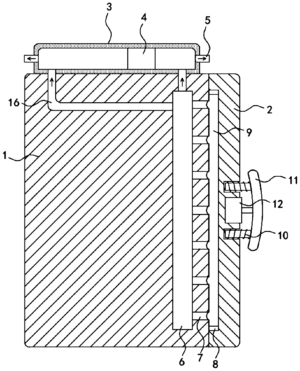
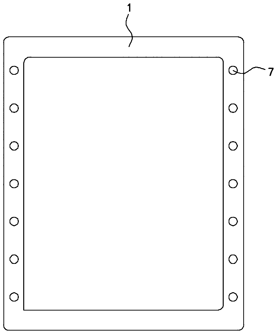
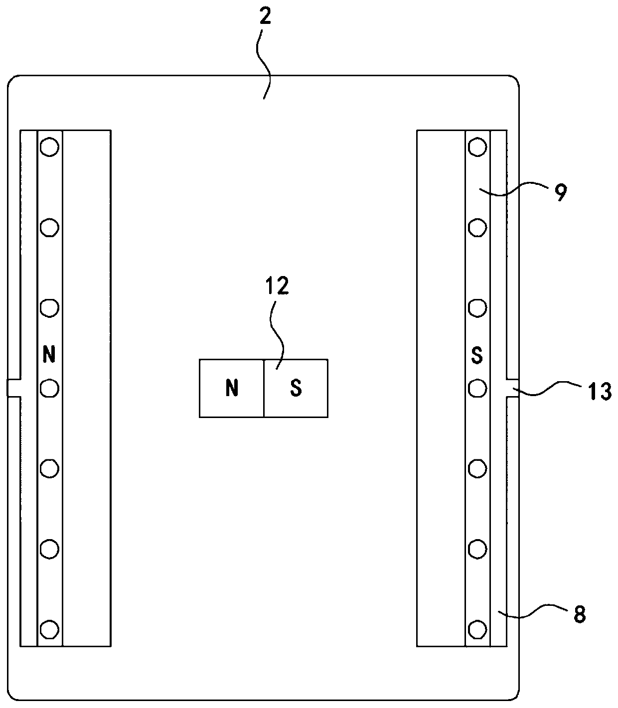
[0021] like Figure 1-3 As shown, a high-performance vehicle-mounted refrigerator for a new energy vehicle includes a box body 1 and a box door 2 hinged on the box body 1. A negative pressure cylinder 3 is fixedly installed on the upper end of the box body 1, and the inner side wall of the negative pressure cylinder 3 The upper seal is slidingly connected with a slider 4, and both ends of the negative pressure cylinder 3 are fixedly connected with a one-way exhaust pipe 5, which only allows the air in the negative pressure cylinder 3 to be discharged to the outside atmosphere. 1 is provided with a negative pressure chamber 6, the negative pressure chamber 6 communicates with the negative pressure cylinder 3 through two one-way suction passages 16, and the one-way suction passage 16 only allows the air in the negative pressure chamber 6 to enter the negative pressure cylinder 3 , two one-way suction passages 16 are respectively arranged on both sides of the slider 4, a pluralit...

Embodiment 2

[0027] like Figure 4 As shown, the difference between this embodiment and Embodiment 1 is that: the outlet ends of the two one-way exhaust pipes 5 are fixedly connected with extension pipes 14, and the lower ends of the extension pipes 14 are extended to the bottom of the box body 1, and The air outlet end of the extension pipe 14 is downward, and the air outlet end of the extension pipe 14 is fixedly equipped with an air nozzle 15, and the air nozzle 15 is conically arranged with the tip downward.

[0028] In this embodiment, when the vehicle accelerates or decelerates, the slider 4 slides in the negative pressure cylinder 3, extrudes the gas in the negative pressure cylinder 3 through the one-way exhaust pipe 5, and the discharged gas passes through the extension pipe 14 and is discharged by the air jet. The nozzle 15 accelerates downward to spray, and at the same time, a reaction force in the opposite direction is given to the air nozzle 15 to offset the inertial force tha...


PUM


Abstract

The invention belongs to the field of new energy automobiles and particularly relates to a high-performance vehicle-mounted refrigerator for a new energy automobile. The high-performance vehicle-mounted refrigerator comprises a box and a box door hinged to the box. A negative pressure barrel is fixedly installed at the upper end of the box. A slider is connected to the inner side wall of the negative pressure barrel slidably in a sealed mode. The two ends of the negative pressure barrel each fixedly communicate with a one-way exhaust pipe. A negative pressure cavity is formed in the box and communicates with the negative pressure barrel through two one-way gas suction channels. The two one-way gas suction channels are formed on the two sides of the slider correspondingly. A plurality of negative pressure holes are formed in the side wall of the negative pressure cavity. The other ends of the negative pressure holes communicate with the outside world. Two sliding grooves are formed in the side wall, close to the box, of the box door. Sealing strips are slidably connected to the side walls of the sliding grooves. The box door can be tightly attached to the box through a negative pressure effect, the box door is prevented from being opened automatically under the inertia effect, the sealing effect between the box door and the box is improved, outward leakage of cold air is prevented, and energy is saved.

Description

technical field [0001] The invention belongs to the field of new energy vehicles, in particular to a high-performance vehicle-mounted refrigerator for new energy vehicles. Background technique [0002] With the progress of society, more and more new energy vehicles have appeared in people's field of vision. While improving the power energy of vehicles, people have also improved the interior comfort of new energy vehicles. Therefore, new energy vehicles Most cars are equipped with car refrigerators to improve the competitiveness of new energy vehicle products. [0003] When the existing car refrigerator is in use, if it is on a complex road surface, the car in the driving state often decelerates or accelerates, causing the door of the car refrigerator to open automatically under the action of inertia, which cannot achieve a good fresh-keeping and cooling effect. The unstable box is easy to shake under the action of inertia, causing danger. The long-term use seal on the door ...

Claims


Application Information

Patent Timeline
IPC IPC(8): F25D11/00F25D23/02F25D23/00B60N3/10F16J15/10F16J15/48
CPCB60N3/104F16J15/10F16J15/48F25D11/00F25D23/00F25D23/028
Inventor 严威
Owner 北京盒子智行科技有限公司
Why Eureka
Try Eureka