Reflective photoplethysmography simulation calibration method and device

A technology of photoplethysmogram and analog calibration, which is applied in the field of biomedical engineering, can solve the problems that the infrared light and red light paths are difficult to separate, and the positions and shapes of light-emitting diodes and photodiodes are different.

Active Publication Date: 2020-02-21
XI AN JIAOTONG UNIV
View PDF7 Cites 5 Cited by
  • Summary
  • Abstract
  • Description
  • Claims
  • Application Information

AI Technical Summary

Problems solved by technology

Due to the limitation of the calibration method, the calibration of the variability of respiration and pulse rate (heart rate) is not yet possible
At the same time, the positions, distances, shapes, and sizes of the light-emitting diodes and photodiodes in the reflective photoplethysmometric wave monitoring devices of various models produced by many manufacturers make the position of the LED and PD between the calibration device and the monitoring device different. Difficult to align
Different light-emitting frequencies and different driving sequences of light-emitting diodes make it difficult to separate the infrared and red light paths and make identification difficult
In the end, it is difficult to produce and manufacture reflective photoelectric volume wave analog calibration devices with uniform specifications and compatible with products from various manufacturers. They can only be customized according to the specifications and requirements of different monitoring devices.
This current situation has greatly restricted the application of reflective photoplethysmography monitoring devices, especially reflective oximeters.

Method used


Image

  • Reflective photoplethysmography simulation calibration method and device
  • Reflective photoplethysmography simulation calibration method and device
  • Reflective photoplethysmography simulation calibration method and device

Examples


Embodiment Construction

[0053] The present invention will be further described in detail below in conjunction with specific embodiments, which are explanations of the present invention rather than limitations.

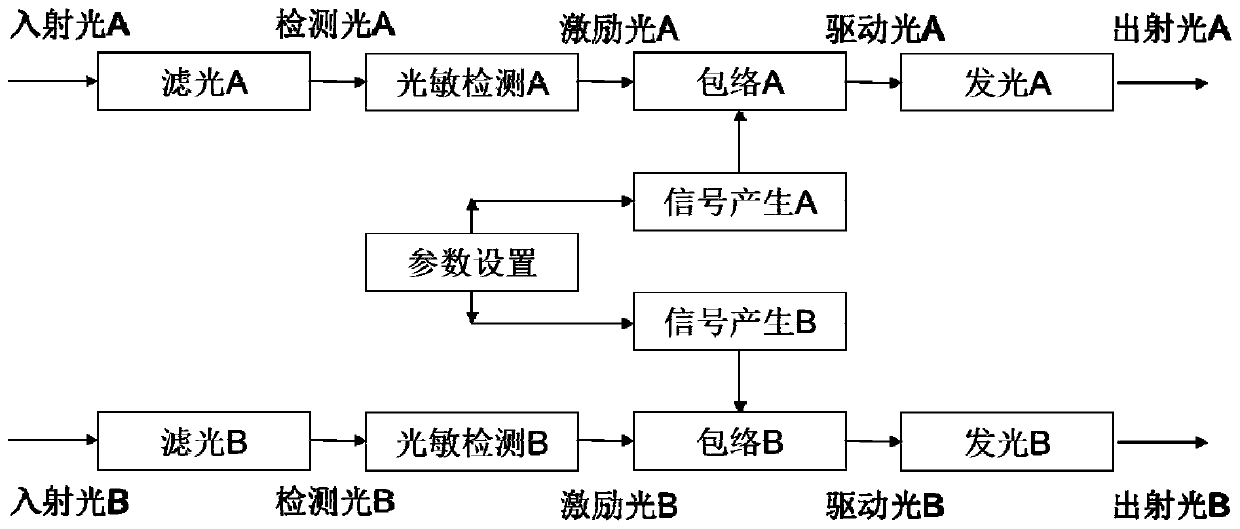
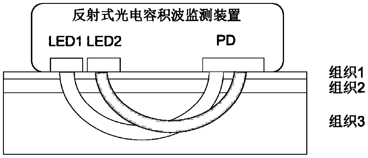
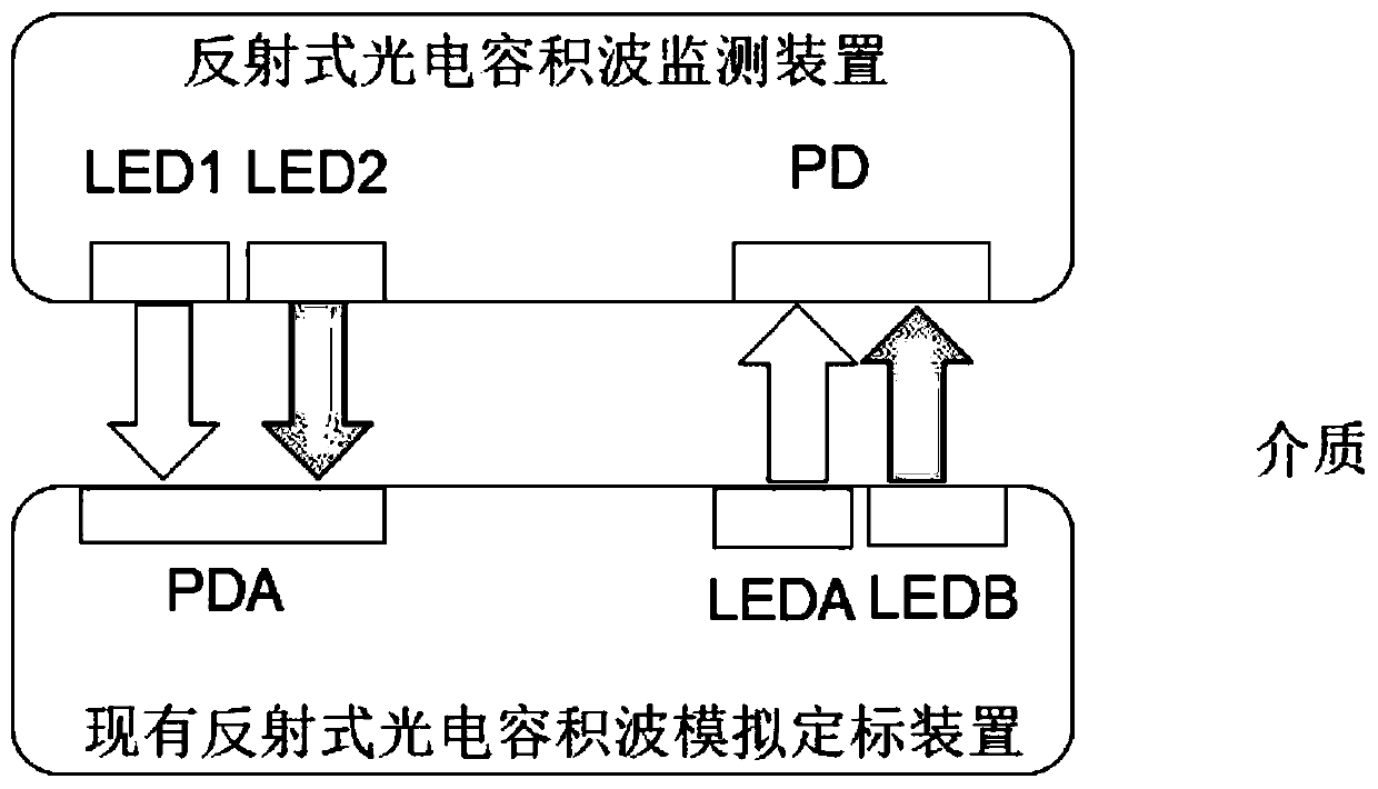
[0054] In the present invention, the synthetic parameters of the simulation are dynamically adjustable, and the simulated photoplethysmographic technology including multi-parameter physiological information such as pulse rate, respiration, pulse rate variability, and blood oxygen saturation solves the problem of the existing reflective photoplethysmographic monitoring device. In the monitoring device of the manufacturer and model, the positions, distances, shapes, sizes, light-emitting frequencies, and light source drive timings of the light source and the detector are different, which makes it difficult to produce, manufacture uniform, and compatible reflections of products from various manufacturers. In order to solve the problems of the photoplethysm wave analog calibration device, a reflec...


PUM


Abstract

The invention discloses a reflective photoplethysmography simulation calibration method and device. According to the method and device, simulation synthesis parameters are dynamically adjustable, standard simulation photoplethysmography containing multi-parameter physiological information such as pulse rate, respiration, pulse rate variability and oxyhemoglobin saturation serves as a detection envelope, and problems in calibrating the pulse rate, respiration, pulse rate variability and oxyhemoglobin saturation at the same time are solved; a pair of optical filters is used to separate infraredlight from red light emitted by a reflective photoplethysmography monitor to solve problems in identification of the infrared light and red light; an infrared light and red LED and an infrared light and red light PD of the calibration device are mounted in the same position to solve the problem in aligning the LED with the PD between the calibration device and the monitoror; and amplitudes of redlight and infrared light pulses emitted by a light emitting device in the calibration device are modulated to the standard simulated reflective photoplethysmography signal envelop according red lightand infrared light driving pulse waveform of the reflective photoplethysmography monitor itself, and the problem that different monitors are different in light emitting frequency and driving sequenceis solved.

Description

technical field [0001] The invention belongs to the field of biomedical engineering, and relates to a reflection-type photoelectric volumetric wave simulation calibration method and device. Background technique [0002] Photoplethysmography contains rich physiological signals including pulse rate, respiration, pulse rate variability and blood oxygen saturation, etc. It is an important detection object for routine medical monitoring, and the accuracy of the relevant physiological information detection results is directly related to Clinical diagnosis and therapeutic effect. Therefore, the research on the photoplethysmometric calibration method and device has been going on until now. [0003] Among them, the documents "Study on Calibration Curve of Pulse Oximeter" and "Development of Calibration Device for Pulse Oximeter" disclose the main measurement indicators of transmission photoplethysmography, calibration curve and calibration device of pulse oximeter, and solve the pro...

Claims


Application Information

Patent Timeline
Patent Type & Authority Applications(China)
IPC IPC(8): G01J1/44G01J3/42
CPCG01J1/44G01J3/42G01J2001/446G01J2003/425
Inventor 陈翔李津王敬川许世一闫相国王珏
Owner XI AN JIAOTONG UNIV
Why Eureka
Try Eureka