Eureka AIR delivers breakthrough ideas for toughest innovation challenges, trusted by R&D personnel around the world.

Optical fiber cable distribution box with core radiation

A heat-dissipating type fiber distribution box technology, applied in the field of fiber distribution box, can solve the problems of poor heat dissipation, affecting the passage of pedestrians, and reducing the use effect, so as to reduce the use effect of optical fibers, prevent the internal temperature from being too high, and enhance heat dissipation Effect

Pending Publication Date: 2020-02-21
杭州昱华科技有限公司
View PDF0 Cites 2 Cited by
  • Summary
  • Abstract
  • Description
  • Claims
  • Application Information

AI Technical Summary

Problems solved by technology

[0003] After the existing optical cable distribution box is installed indoors, it only dissipates heat through some cooling holes, and its cooling effect is not good, causing the temperature in the box to be too high, resulting in a reduced use effect; sometimes a cooling fan is installed for cooling. The practicability is not strong, the internal heat dissipation circulation effect is not significant, and it is inconvenient to install the fiber distribution box, and the door is easy to open automatically, which affects pedestrians in the corridor. box

Method used


Image

  • Optical fiber cable distribution box with core radiation
  • Optical fiber cable distribution box with core radiation
  • Optical fiber cable distribution box with core radiation

Examples


Embodiment

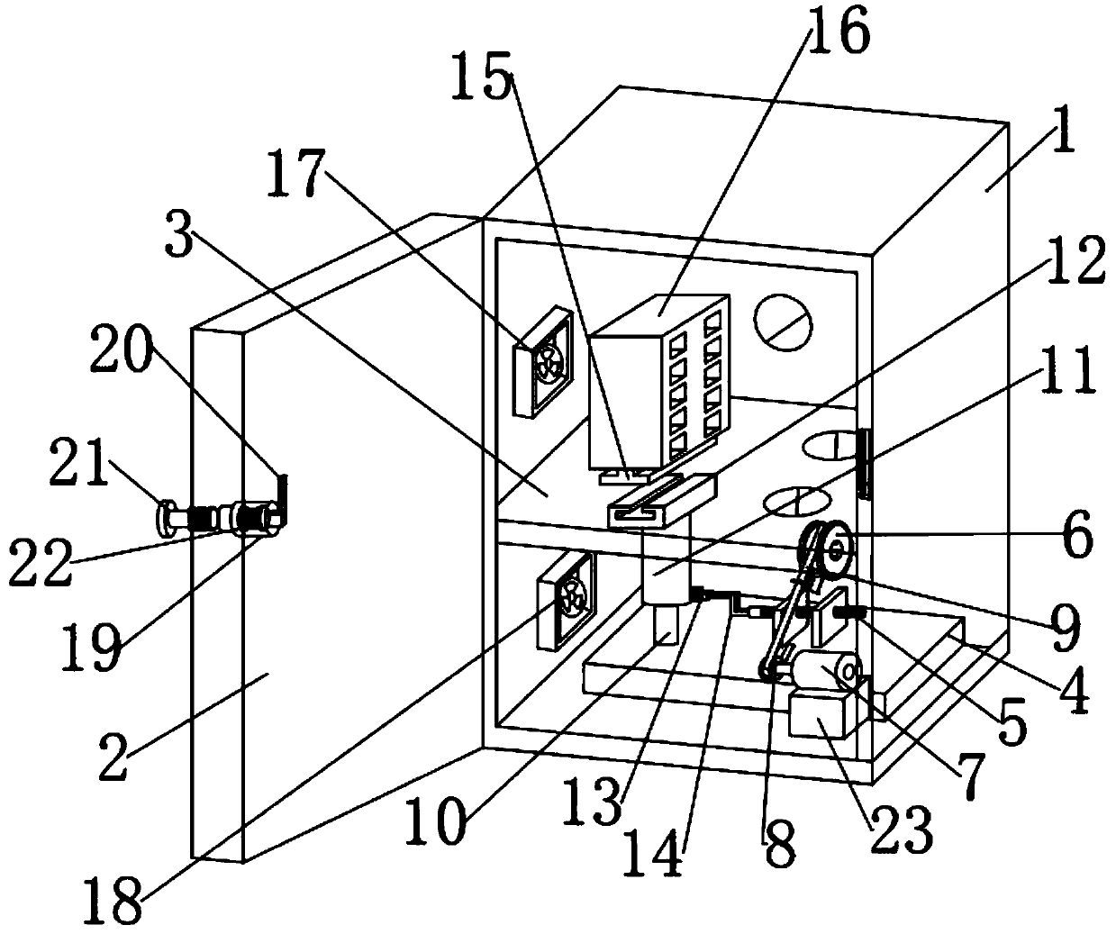
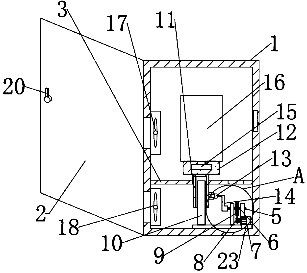
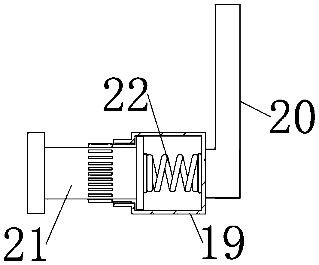
[0040] Embodiment: Attached by instruction manual Figure 1-5 It can be seen that, firstly, after the equipment is powered on, the fiber distribution box 16 is installed on the rail 12 through the clamping block 15, the air is blown to the fiber distribution box 16 through the first fan 17, and enters the lower layer of the box through the through hole of the partition plate 3, And through the second fan 18, the heat dissipation of the rapid cycle is formed; at the same time, the drive of the motor 7 on the pad 23 is controlled, and the drive belt 9 driven by the first transmission wheel 6 and the second transmission wheel 8 is set to drive the mounting table 4. The adapter rod 14 at one end of the shaft rod 5 on the board rotates, and through the flexible connection with the adapter block 13, the lifting cylinder 11 moves up and down on the limit rod 10, and then drives the fiber distribution box 16 to align with the first fan 17 moves up and down to make it more fully dissip...


PUM


Abstract

The invention discloses an optical fiber cable distribution box with core radiation. The optical fiber cable distribution box comprises: a box body and a door body. The box body is a box body structure without a front wall face, and a transmission line hole is opened on a rear side wall of the box body. The door body is movably arranged on a front wall edge of the box body. The invention relates to the technical field of cable distribution boxes. Air is blown into a cable distribution box by using a first fan, the air enters a lower layer inside the box through a through-hole of a baffle plate, and the air is drawn out by a using a second fan to form heat dissipation with rapid circulation. In addition, driving of a motor is controlled, to enable an elevator cylinder to move up and down ona limiting lever, so as to drive the cable distribution box to align with the first fan to move up and down, so that the cable distribution box is cooled more comprehensively by wind force. Further,an actuating arm can be pressed, and the actuating arm is rotated to enable a locking bar to rotate anticlockwise in a lockhole of the box body to perform locking. According to the design, not only circulated wind can be formed to reduce temperature, enhance radiating capability, and prevent optical fiber using effects from being reduced due to excessively high inner temperature, but also the doorbody can be conveniently closed and locked, to prevent corridor pedestrians from being affected.

Description

technical field [0001] The invention relates to the technical field of fiber distribution boxes, in particular to a core heat dissipation type fiber distribution box. Background technique [0002] The optical fiber distribution box is an interface device used to connect the main optical cable and the distribution optical cable outdoors, in the corridor or indoors. The optical fiber distribution box must be able to work reliably in the specified environment, and its box can withstand a vertical pressure not greater than 500N ;The internal multi-core depends on the number of fiber distribution boxes that can disperse the lines. The more disperse lines, the higher the heat of its own work; [0003] After the existing optical fiber distribution box is installed indoors, it only dissipates heat through some cooling holes, and its cooling effect is not good, causing the temperature in the box to be too high, resulting in a reduced use effect; sometimes a cooling fan is installed...

Claims


Application Information

Patent Timeline
IPC IPC(8): G02B6/44
CPCG02B6/4446
Inventor 羊昱霖刘郑晓朱军伟羊忠良倪献明
Owner 杭州昱华科技有限公司
Why Eureka
Eureka Blog
Learn More