Cable connector

A cable connector and cable technology, which is applied in the direction of connection, conductive connection, electrical component connection, etc., can solve the problems of poor tensile performance of cable connectors, affecting connection stability, and high resistance of contact positions. It is not easy to achieve Breakage, high fixing strength, and the effect of improving stability

Active Publication Date: 2020-02-21
SHENZHEN XFANIC TECH CO LTD
View PDF6 Cites 1 Cited by
  • Summary
  • Abstract
  • Description
  • Claims
  • Application Information

AI Technical Summary

Problems solved by technology

[0002] The traditional piercing type cable connector generally uses a push rod to pierce a single conductive piece into the cable. The conductive material of the cable itself has plasticity, so the cable connector with this structure has poor tensile performance and contact There are relatively few points, and the contact position is easily overheated due to high resistance, which affects the stability of the connection

Method used


Image

  • Cable connector
  • Cable connector

Examples


Embodiment Construction

[0019] The present invention is described in further detail now in conjunction with accompanying drawing. These drawings are all simplified schematic diagrams, which only illustrate the basic structure of the present invention in a schematic manner, so they only show the configurations related to the present invention.

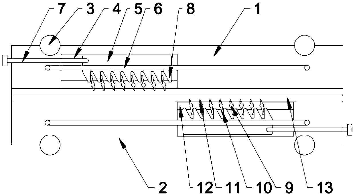
[0020] like figure 1 and figure 2 As shown, the present invention is a cable connector, including an upper splint and a lower splint, cable clamps are arranged on the upper splint and the splint, and the cable clamps of the upper splint and the lower splint are symmetrical about the center Arrangement, wherein a strip-shaped cable inlay groove is respectively arranged on the upper splint and the lower splint; the cable clamp is located in the upper splint and the lower splint at the bottom of the cable inlay groove; the cable clamp It includes a moving slider, and a sliding groove for sliding the moving slider is arranged inside the upper splint and the low...


PUM


Abstract

The invention relates to a cable connector, and the connector comprises an upper clamping plate and a lower clamping plate; cable holders are arranged on the upper clamping plate and the lower clamping plate, wherein long-strip-shaped cable inlaying grooves are formed in the upper clamping plate and the lower clamping plate respectively. Each cable holder comprises a movable sliding block. Slidinggrooves used for sliding of the movable sliding blocks are formed in the upper clamping plate and the lower clamping plate. A rotating frame is arranged on the inner wall of the openings of the sliding grooves; a plurality of inserting pieces are arranged on the rotating frame in a linear array manner; a rotating shaft is integrally arranged in the middle of the inserting pieces, the rotating shaft is rotationally connected with a rotating hole in the rotating frame, a poking piece is arranged on one side wall of the rotating shaft, a plurality of pushing pieces are fixed to the bottom of themovable sliding block in a linear array mode, the poking piece makes contact with the pushing pieces, and a cable inserting piece is arranged on the side wall of the other side, corresponding to thepoking piece, of the rotating shaft; pushing screws are further arranged at one end of the upper clamping plate and one end of the lower clamping plate and are in threaded connection with the upper clamping plate and the lower clamping plate, and the ends of the pushing screws make contact with the movable sliding blocks.

Description

technical field [0001] The invention relates to a cable connector and belongs to the field of conductive equipment. Background technique [0002] The traditional piercing type cable connector generally uses a push rod to pierce a single conductive sheet into the cable. The conductive material of the cable itself has plasticity, so the cable connector with this structure has poor tensile performance and contact There are relatively few points, and the contact position is easily overheated due to high resistance, which affects the connection stability. Contents of the invention [0003] The technical problem to be solved by the present invention is to provide a cable connector by overcoming the technical problems in the prior art. [0004] The technical solution adopted by the present invention to solve its technical problems is: [0005] A cable connector, comprising an upper splint and a lower splint, cable clamps are arranged on the upper splint and the splint, and the ...

Claims


Application Information

Patent Timeline
Patent Type & Authority Applications(China)
IPC IPC(8): H01R11/01H01R11/09H01R4/2475
CPCH01R4/2475H01R11/01H01R11/09
Inventor 徐陈花
Owner SHENZHEN XFANIC TECH CO LTD
Why Eureka
Try Eureka