Flat wire motor winding in-groove structure with conductors with different thicknesses

A technology of motor winding and internal structure, which is applied to the shape/style/structure of winding conductors, and can solve the problems of large thickness of flat copper wire, skin effect, and many layers

Pending Publication Date: 2020-02-21
NANJING HAOLONG ELECTRONICS CO LTD
View PDF0 Cites 0 Cited by
  • Summary
  • Abstract
  • Description
  • Claims
  • Application Information

AI Technical Summary

Problems solved by technology

[0003] However, due to the large thickness of the flat copper wire, under the action of the high-frequency magnetic field of the motor, a more serious skin effect will be produced, resulting in an increase in the AC resistance of the conductor, which will increase the copper loss of the moto

Method used


Image

  • Flat wire motor winding in-groove structure with conductors with different thicknesses
  • Flat wire motor winding in-groove structure with conductors with different thicknesses

Examples


Embodiment 1

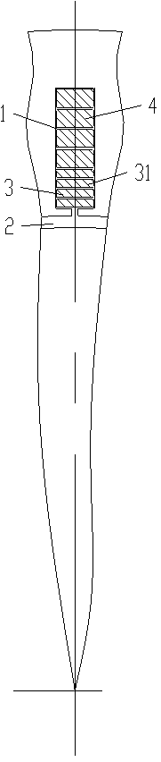
[0020] see figure 1 As shown in the slot structure of flat wire motor windings with conductors of different thicknesses, there are 6 conductors in the wire slot 1 along the radial direction of the motor, and the two conductors near the air gap 2 are composite layer conductors 3, far away from the air gap. The four conductors of gap 2 are integral layer conductors 4 . The composite layer conductor 3 is composed of two layers of sub-conductors 31 arranged in the radial direction of the motor, and the integral layer conductor 4 is an integral layer in the radial direction of the motor. The thickness of the sub-conductors 31 in the radial direction of the motor is smaller than the thickness of the overall layer conductor 4 . The cross-sectional area of ​​the composite layer conductor 3 composed of two sub-conductors 31 is the same as that of the integral layer conductor 4 .

Embodiment 2

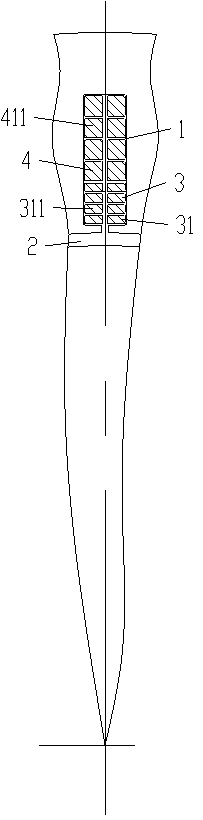
[0022] see figure 1 As shown in the slot structure of flat wire motor windings with conductors of different thicknesses, there are 6 conductors in the wire slot 1 along the radial direction of the motor, and the two conductors near the air gap 2 are composite layer conductors 3, far away from the air gap. The four conductors of gap 2 are integral layer conductors 4 . The composite layer conductor 3 is composed of two layers of sub-conductors 31 arranged in the radial direction of the motor, and each sub-conductor 31 is composed of two grandchildren 311 arranged in the circumferential direction of the motor. The integral layer conductor 4 is an integral layer in the radial direction of the motor, and is composed of two sub-conductors 411 arranged in the circumferential direction of the motor. The thickness of the grand-conductor 311 in the radial direction of the motor is smaller than that of the sub-conductor 411 . The cross-sectional area of ​​the composite layer conductor ...


PUM


Abstract

The invention provides a flat wire motor winding in-groove structure with conductors with different thicknesses. The structure can be used to reduce a skin effect and a motor copper loss, and has a high groove filling rate and high efficiency. A plurality of conductors are arranged in a wire groove in a radial direction of a motor. At least one conductor close to an air gap is composed of more than two layers of sub-conductors arranged in the radial direction of the motor. At least one conductor, far away from the air gap, is an integral layer in the radial direction of the motor, the thickness of each sub-conductor in the radial direction of the motor is smaller than that of the integral layer far away from the air gap, and a sectional area of each conductor composed of the sub-conductors, close to the air gap, is the same as that of the integral layer conductor far away from the air gap.

Description

technical field [0001] This patent relates to flat wire motor windings, specifically, the structure of the windings in wire slots. Background technique [0002] With the development of power motors, the use of flat section conductors in power motors has become a development trend. Flat wire motor windings are formed by connecting flat conductors (flat copper wires) that pass through the wire slots on the iron core at the ends protruding out of the wire slots. In the slot structure of the conventional flat wire motor winding, there are multiple flat copper wires with the same thickness in the wire slot along the radial direction of the motor. [0003] However, due to the large thickness of the flat copper wire, under the action of the high-frequency magnetic field of the motor, a more serious skin effect will occur, resulting in an increase in the AC resistance of the conductor, increasing the copper loss of the motor, and reducing the efficiency. In order to solve this One...

Claims


Application Information

Patent Timeline
IPC IPC(8): H02K3/12H02K3/28H02K3/04
CPCH02K3/04H02K3/12H02K3/28
Inventor 林中尉
Owner NANJING HAOLONG ELECTRONICS CO LTD
Why Eureka
Try Eureka