Traffic sign mounting structure

A technology for installation structure and sign boards, applied in the field of sign boards, can solve the problems of slow installation efficiency, actual position error of anchor bolts, bending or tilting of anchor bolts, etc., to improve efficiency, reduce the number of times, and reduce the use of the effect of time

Inactive Publication Date: 2020-02-25
陕西瑞道交通工程有限公司
View PDF7 Cites 4 Cited by
  • Summary
  • Abstract
  • Description
  • Claims
  • Application Information

AI Technical Summary

Problems solved by technology

[0005] The above existing technical solutions have the following defects: when hoisting the column, after the welded column and the upper flange are hoisted above the bottom flange, the anchor bolts set in advance on the upper flange need to pass through The opening of the hole is aligned with the anchor bolts to complete the installation of the column and the upper flange. However, the anchor bolts are placed together when pouring the mounting seat, and some of the anchor bolts exposed from the mounting seat will be bent or tilted. And when opening holes on the upper flange, there will be errors with the actual position of the anchor bolts. Therefore, when aligning the holes on the upper flange with the anchor bolts, it is necessary to compare them during the hoisting process. The deviation between the holes on the upper flange and the anchor bolts is used to correct the anchor bolts. The adjustment process often requires repeated lifting of the column and the upper flange to directly above the anchor bolts for comparison before lifting. Correct the anchor bolts directly above the anchor bolts, and the installation efficiency is slow

Method used


Image

  • Traffic sign mounting structure
  • Traffic sign mounting structure
  • Traffic sign mounting structure

Examples


Embodiment Construction

[0033] The present invention will be described in further detail below in conjunction with the accompanying drawings.

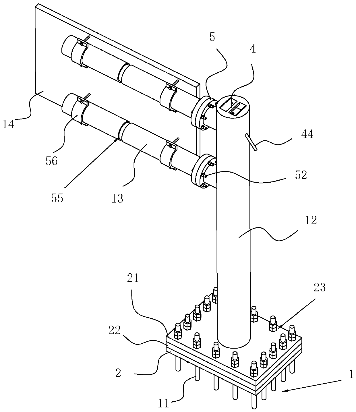
[0034] Such as figure 1 As shown, it is a traffic sign mounting structure disclosed by the present invention, which includes a mounting base 1 that goes deep into the ground and a column 12 installed on the mounting base 1. Embedded plate 2, embedded plate 2 is provided with anchor bolts 11 distributed along the circumferential direction of embedded plate 2, and one end of column 12 is welded with mounting plate 21 made of steel with the upper surface of mounting seat 1 attached and made of steel. There is a first opening 23 for the anchor bolts 11 to pass through, the end of the column 12 away from the mounting plate 21 is provided with a traffic sign 14, and the column 12 is provided with at least two cross bars connecting the traffic sign 14 made of steel 13. The traffic sign 14 is connected to the cross bar 13 by including. In this embodiment, two cross ...


PUM


Abstract

The invention relates to a traffic sign mounting structure in the sign field, and aims to solve the problem of the mounting efficiency of traffic signs. The traffic sign mounting structure comprises amounting seat and a stand column, wherein a pre-buried plate is arranged on the mounting seat, foundation bolts distributed in the circumferential direction of the pre-buried plate are arranged on the pre-buried plate, one end of the stand column is provided with a mounting plate in a welded mode, the mounting plate is attached to the upper surface of the mounting base, first openings allowing the foundation bolts to penetrate therethrough are formed in the mounting plate, a traffic sign is arranged at the end, far away from the mounting plate, of the stand column, the side, away from the stand column, of the mounting plate is provided with an auxiliary plate consistent with the mounting plate, the auxiliary plate is provided with second openings corresponding to the positions of the first openings, the auxiliary plate is provided with a guide rod which is perpendicular to the auxiliary plate in the axial direction, a first through hole allowing the guide rod to slide in the axial direction of the guide rod is formed in the center of the auxiliary plate, the inner wall of the first through hole is attached to the outer wall of the guide rod, and the center of the pre-buried plateis provided with a second through hole attached to the outer wall of the guide rod. The mounting structure has the effect of improving the mounting efficiency of the traffic sign.

Description

technical field [0001] The invention relates to the technical field of signboards, in particular to a traffic signboard installation structure. Background technique [0002] Road traffic signs are graphic symbols that display traffic regulations and road information, and are used to manage traffic and indicate driving directions to ensure smooth roads and safe driving. It is generally composed of several parts such as a sign base plate, a sign surface, a column, fasteners, and a foundation. General signboards are coated reflective materials used to display traffic regulations and road information. When used at night, they can only be displayed by lighting. [0003] The existing notification number is that the Chinese patent of CN209011020U discloses a kind of traffic sign board and its installation structure, including: the mounting seat for installing the traffic sign board that goes deep into the ground; An assembled mounting assembly for assembling the column and the mo...

Claims


Application Information

Patent Timeline
Patent Type & Authority Applications(China)
IPC IPC(8): E01F9/696E01F9/623
CPCE01F9/623E01F9/696
Inventor 陈言高陈永球陈海相陈永华
Owner 陕西瑞道交通工程有限公司
Why Eureka
Try Eureka