Electrical control cabinet terminal strip

A technology for electrical control cabinets and terminal blocks, applied in electrical components, circuits, conductive connections, etc., can solve the problems of time-consuming and laborious wires, damage to the outer wall of the wire harness, affecting the conductive performance of wires, etc., to ensure the connection effect and avoid bolt slippage. Wire, improve the effect of wiring efficiency

Active Publication Date: 2020-02-25
杭州铭伟斯电气有限公司
View PDF5 Cites 8 Cited by
  • Summary
  • Abstract
  • Description
  • Claims
  • Application Information

AI Technical Summary

Problems solved by technology

[0002] The wiring harness inside the electrical cabinet is connected and fixed by terminal blocks; however, the space inside the electrical cabinet is small, and the existing wiring harness is not easy to plug in and fix inside the terminal block, and most of the existing wiring harnesses are single-to-one It is inserted into the terminal block and fixed by screwing the fixing bolts. However, it is time-consuming and labor-intensive to fix the connected wires by single screwing the bolts, and it is easy to cause slippage when the bolts are twisted back and forth, resulting in unreliable fixing of the ends of the wire harness,

Method used


Image

  • Electrical control cabinet terminal strip
  • Electrical control cabinet terminal strip
  • Electrical control cabinet terminal strip

Examples


Embodiment Construction

[0020] Embodiments of the present invention will be described below with reference to the drawings. In the process, in order to ensure the clarity and convenience of illustration, we may exaggerate the width of the lines or the size of the constituent elements in the diagram.

[0021] In addition, the following terms are defined based on the functions in the present invention, and may be different according to the user's or operator's intention or practice. Therefore, these terms are defined based on the entire content of this specification.

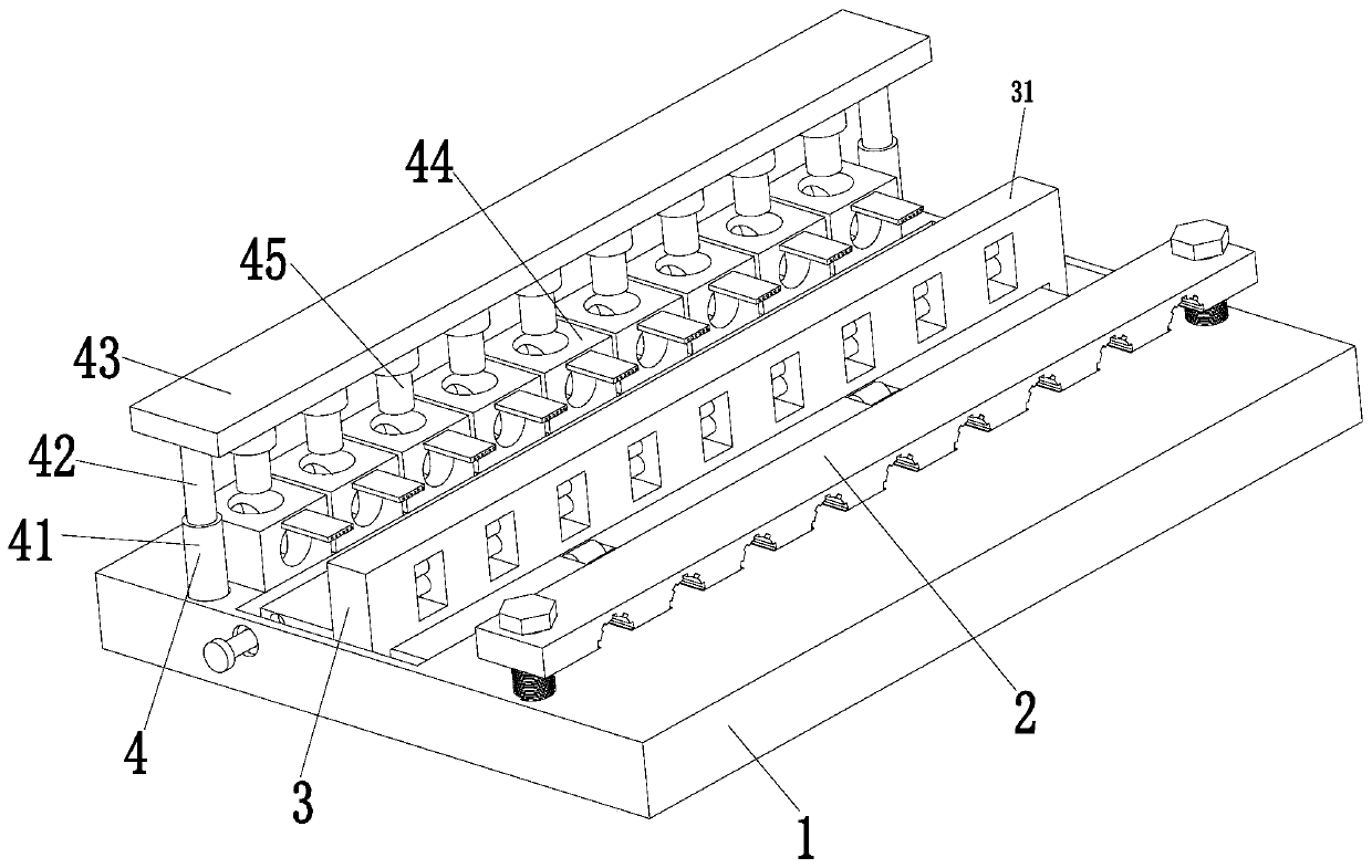
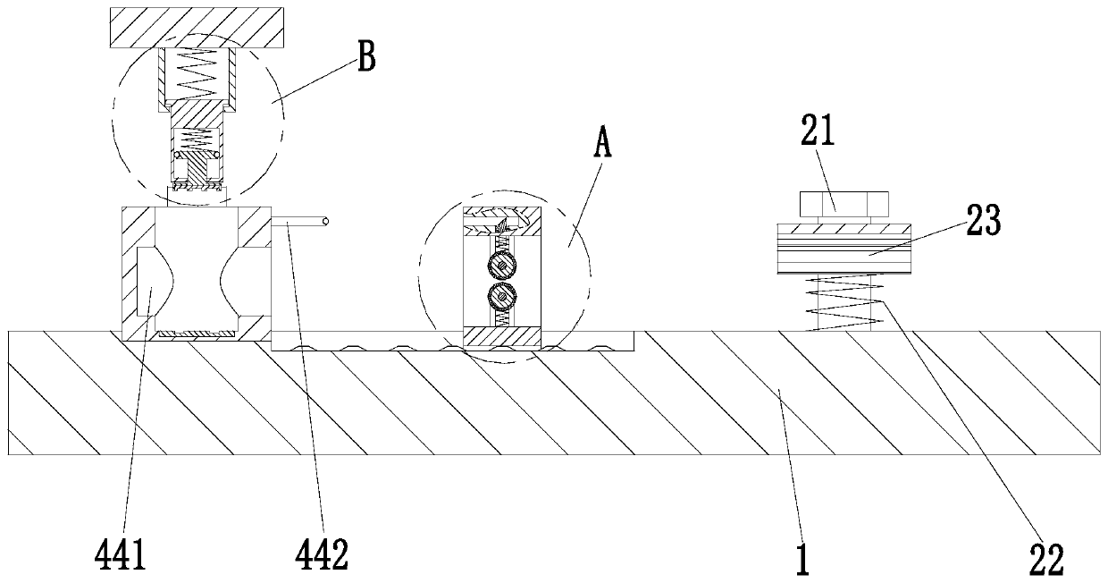
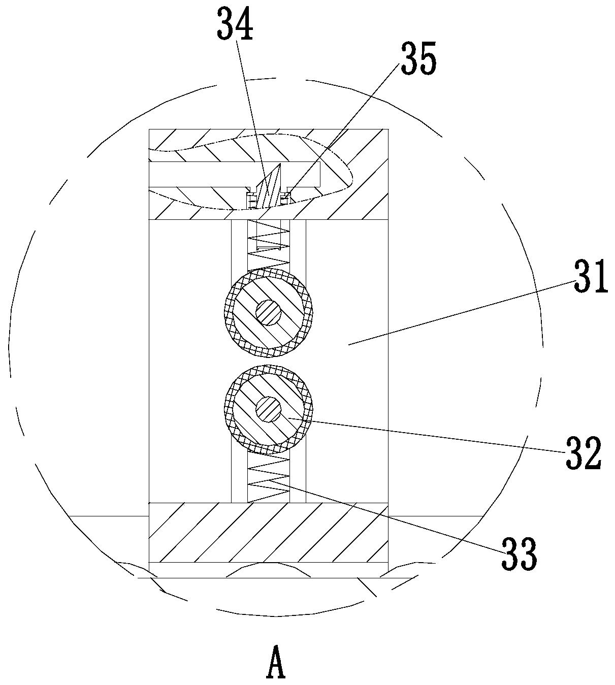
[0022] Such as Figure 1 to Figure 4 As shown, a terminal block of an electrical control cabinet includes a fixed plate 1, a fixed member 2, a limiting member 3 and a terminal connecting member 4; a rectangular groove is opened in the middle of the fixed plate 1, and is located on the front and rear outer walls of the rectangular groove. There is a sliding groove, the limiting member 3 is installed in the sliding groove of the fixed pl...


PUM


Abstract

The invention provides an electrical control cabinet terminal strip. The electrical control cabinet terminal strip comprises a fixing plate, a fixing component, a limiting component and a terminal connecting component. Thus, the problems that the existing wire harness is inconvenient to be inserted into the terminal strip for fixation, the existing wire harnesses are mostly inserted into a terminal strip in a one-to-one correspondence mode and are fixed by screwing fixing bolts, however, time and labor are consumed when connected wires are fixed by screwing single bolts, wire slipping is proneto occurring when the bolts are screwed in a rotating mode, and therefore the ends of the wire harnesses are not firmly fixed and are prone to loosening, the use is influenced, and moreover, the outer wall of the wire harness needs to be fixed through a buckle after a conventional wire is connected to the terminal strip, thereby preventing the wire harness from being separated from a connection hole of the terminal strip when the wire harness is pulled by an external force, however, existing fixing mostly adopts single fixing and is inconvenient to use, and an existing mode of fixing the outer wall of the wire harness easily causes damage to the outer wall of the wire harness and affects the conductivity of the wire can be solved.

Description

technical field [0001] The invention relates to the technical field of electrical cabinets, in particular to a terminal block of an electrical control cabinet. Background technique [0002] The wiring harness inside the electrical cabinet is connected and fixed by terminal blocks; however, the space inside the electrical cabinet is small, and the existing wiring harness is not easy to plug in and fix inside the terminal block, and most of the existing wiring harnesses are single-to-one It is inserted into the terminal block and fixed by screwing the fixing bolts. However, it is time-consuming and labor-intensive to fix the connected wires by single screwing the bolts, and it is easy to cause slippage when the bolts are twisted back and forth, resulting in unreliable fixing of the ends of the wire harness, resulting in The connected wires are easy to loosen, resulting in unsmooth power; affecting the use, and the existing wires need to be fixed on the outer wall of the wire h...

Claims


Application Information

Patent Timeline
IPC IPC(8): H01R9/24
CPCH01R9/24
Inventor 王斌斌金严
Owner 杭州铭伟斯电气有限公司
Why Eureka
Try Eureka