
Positioning clamp for cavity plate structure

A technology for positioning fixtures and cavity plates, which is applied in the direction of manufacturing tools, auxiliary devices, vehicle parts, etc., can solve problems that affect product accuracy, difficulty in ensuring matching accuracy, and difficulty in positioning cavity plate structures, and achieve the effect of overcoming difficult positioning

Active Publication Date: 2020-02-28
ANHUI JIANGHUAI AUTOMOBILE GRP CORP LTD
View PDF8 Cites 0 Cited by
  • Summary
  • Abstract
  • Description
  • Claims
  • Application Information

AI Technical Summary

Problems solved by technology

[0003] Based on this, the present invention provides a positioning fixture for a cavity plate structure, which aims to solve the problem of difficult positioning of the cavity plate structure in the traditional technology, difficulty in ensuring matching accuracy, and affecting product accuracy.

Method used


Image

  • Positioning clamp for cavity plate structure
  • Positioning clamp for cavity plate structure
  • Positioning clamp for cavity plate structure

Examples


Embodiment Construction

[0034] The following will clearly and completely describe the technical solutions in the embodiments of the present invention with reference to the accompanying drawings in the embodiments of the present invention. Obviously, the described embodiments are only part of the embodiments of the present invention, not all of them. Based on the embodiments of the present invention, all other embodiments obtained by persons of ordinary skill in the art without creative efforts fall within the protection scope of the present invention.

[0035] It should be noted that if there is a directional indication (such as up, down, left, right, front, back, top, bottom, etc.) in the embodiment of the present invention, the directional indication is only used to explain the position in a certain posture ( As shown in the accompanying drawings), if the specific posture changes, the directional indication will also change accordingly.

[0036] In addition, if there are descriptions involving "fir...


PUM


Abstract

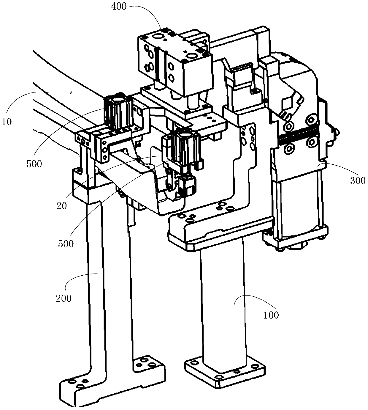
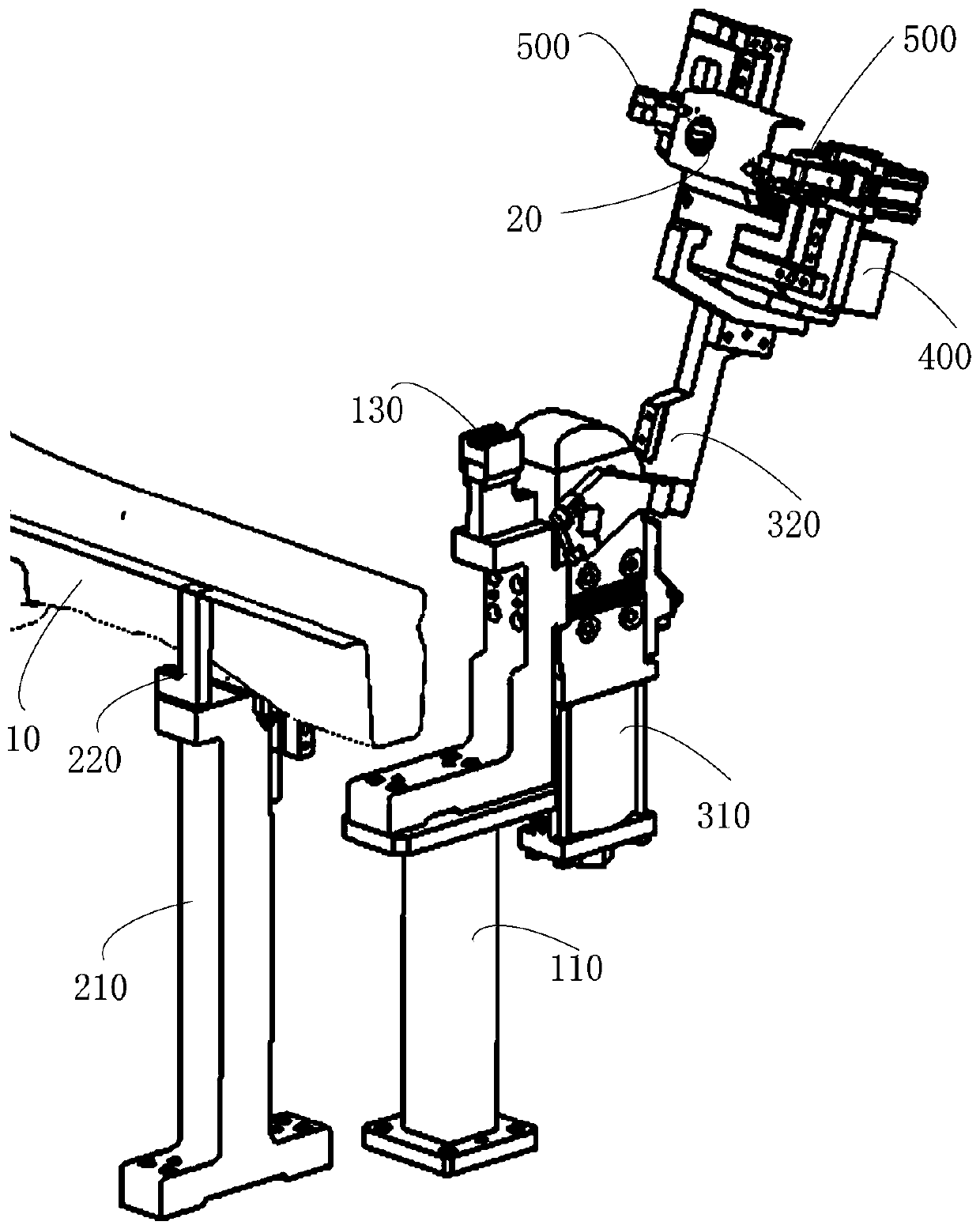
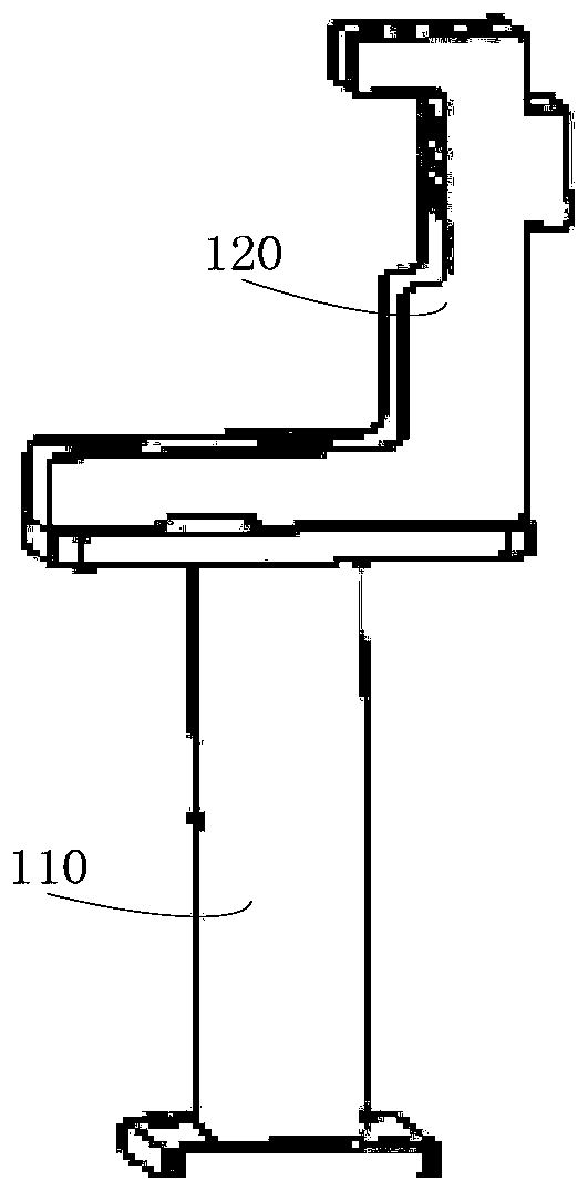
The invention relates to a positioning clamp for a cavity plate structure. The positioning clamp comprises a supporting base and a multi-stage positioning and clamping mechanism arranged on the supporting base; the supporting base comprises a first supporting seat and a second supporting seat arranged apart from the first supporting seat; and the second supporting seat is used for clamping a platebeam structure with a cavity; the multi-stage positioning and clamping mechanism comprises a first-stage rotary positioning and clamping structure arranged on the first supporting seat, a second-stage lifting positioning and clamping structure arranged on the first-stage rotary positioning and clamping structure and a third-stage rotary positioning and clamping structure arranged on the second-stage lifting positioning and clamping structure; and the third-stage rotary positioning and clamping structure is used for clamping a lapping plate and being matched with the second supporting seat. The positioning clamp aims to solve the problem that the structure of a hollow cavity plate is difficultly positioned, the matching precision is difficult to ensure, and the precision of a product is influenced in a traditional technology.

Description

technical field [0001] The invention relates to the field of fixture technology, in particular to a positioning fixture with a cavity plate structure. Background technique [0002] There are some typical cavity plate structures in the automobile body-in-white structure, such as the structure formed by setting lap plates suspended inside the U-shaped beam. And when welding the lap plate to the inside of the U-shaped beam (inner cavity), it needs to be positioned first. However, this cavity plate structure is relatively difficult to locate, and it is difficult to ensure the matching accuracy, which affects the product accuracy. Contents of the invention [0003] Based on this, the present invention provides a positioning fixture for a cavity plate structure, which aims to solve the problems of difficult positioning of the cavity plate structure in the traditional technology, difficulty in ensuring matching accuracy, and affecting product accuracy. [0004] To achieve the a...

Claims


Application Information

Patent Timeline
Patent Type & Authority Applications(China)
IPC IPC(8): B23K37/04
CPCB23K37/0443B23K2101/006
Inventor 何瑞光郑心荣王学敏熊燕
Owner ANHUI JIANGHUAI AUTOMOBILE GRP CORP LTD
Learn More