Steel cable tensioning structure

A steel cable tensioning technology, which is applied in the field of steel cable tensioning structure and tensioning structure, can solve the problems of poor stability of single wheel control, complicated control action, increasing the length of steel cable path, etc., and achieves convenient installation and disassembly, and flexible use Convenience and good stability

Inactive Publication Date: 2020-02-28
徐州易尚饰家装饰工程有限责任公司
View PDF12 Cites 2 Cited by
  • Summary
  • Abstract
  • Description
  • Claims
  • Application Information

AI Technical Summary

Problems solved by technology

[0002] At present, when the equipment is pulled and driven, steel cables are mostly used for transmission. When the transmission is pulled, the steel cables are prone to slack. In order to ensure its pulling and transmission efficiency, it needs to be tensioned. The existing tensioning structure is mainly Use the single wheel to move to one side to increase the path length of the steel cable, and then achieve the purpose of tensioning, but the control stability of the single wheel is poor, and the range that can adjust the tension is limited by the moving stroke of the single wheel. Secondly, it needs to be installed on the Steel cables are tensioned at a specific location, and the cost of maintenance and protection is high
[0003] Publication number CN203922556U discloses a helicopter winch cable tensioning device, which includes: a motor capable of providing constant torque, a tensioning wheel and a support wheel; the motor is connected with the tensioning wheel to provide rotational power for the tensioning wheel ; The circumference of the tensioning wheel can abut against the circumference of the support wheel, and the winch cable is clamped between the circumference of the tensioning wheel and the circumference of the support wheel, and hangs vertically. The structure of the device is complex, and the tensioning wheel is driven by a motor Deflection, complicated control action

Method used


Image

  • Steel cable tensioning structure
  • Steel cable tensioning structure
  • Steel cable tensioning structure

Examples


Embodiment Construction

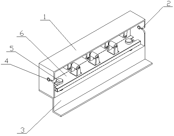
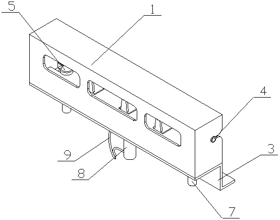
[0016] The steel cable tensioning structure of the present invention is realized in this way: the steel cable tensioning structure of the present invention is composed of a main body device and a tensioning device, and the main body device is composed of an upper box body (1), a side guide groove (2), a lower supporting plate (3 ) and a transverse guide sleeve (4), the upper box (1) is a rectangular box structure, one side and the bottom of the upper box (1) are open, and the lower supporting plate (3) It consists of a horizontal plate and an L-shaped plate, one side of the horizontal plate is vertically connected to one end of the L-shaped plate, the other end of the L-shaped plate is bent away from the horizontal plate, and the horizontal plate is fixed on the upper box The bottom of the body (1), the two ends of the upper box (1) are respectively provided with side guide grooves (2), and one end of the side guide grooves (2) runs through one side of the upper box (1), so Th...


PUM


Abstract

The invention discloses a steel cable tensioning structure. According to the steel cable tensioning structure, through staggered extrusion of an upper pressing wheel and a lower pressing wheel, the path length of a steel cable is increased, tensioning is achieved, multi-wheel movement is achieved, and the control stability is good. The steel cable tensioning structure is characterized in that an upper box body is of a rectangular box body structure, wherein one side and the bottom of the upper box body are open; a lower supporting plate is composed of a transverse plate and an L-shaped plate;one side of the transverse plate is perpendicularly connected with one end of the L-shaped plate; the other end of the L-shaped plate is bent away from the transverse plate; the transverse plate is fixedly arranged at the bottom of the upper box body; side guide grooves are formed in the two ends of the upper box body correspondingly; one of the ends of the side guide grooves penetrates through one side of the upper box body; transverse guide sleeves are arranged at the other ends of the side guide grooves; notches are formed in the transverse guide sleeves, and the notches correspond to the side guide grooves; a plurality of observation grooves are formed in the other side of the upper box body; the width of the opening parts of the side guide grooves is gradually increased; and the groove surfaces of the opening parts are arc-shaped surfaces.

Description

technical field [0001] The steel cable tensioning structure of the invention relates to a tensioning structure for tensioning steel cables, and belongs to the field of mechanical engineering. In particular, it relates to a tensioning structure with good control stability and multi-wheel movement, through the interlaced extrusion of the upper pressing wheel and the lower cam, so that the path length of the steel cable is increased and tensioned. Background technique [0002] At present, when the equipment is pulled and driven, steel cables are mostly used for transmission. When the transmission is pulled, the steel cables are prone to slack. In order to ensure its pulling and transmission efficiency, it needs to be tensioned. The existing tensioning structure is mainly Use the single wheel to move to one side to increase the path length of the steel cable, and then achieve the purpose of tensioning, but the control stability of the single wheel is poor, and the range of tensi...

Claims


Application Information

Patent Timeline
Patent Type & Authority Applications(China)
IPC IPC(8): B25B25/00
CPCB25B25/00
Inventor 不公告发明人
Owner 徐州易尚饰家装饰工程有限责任公司
Why Eureka
Try Eureka