
Timber feeding device for furniture production

A wood feeding and furniture technology, applied in the direction of manufacturing tools, wood processing appliances, special forming/shaping machines, etc., can solve the problems of inconvenience, potential safety hazards, and easy deviation of wood, so as to facilitate transportation and improve cutting efficiency effect

Inactive Publication Date: 2020-02-28
北京世纪京洲家具有限责任公司
View PDF7 Cites 1 Cited by
  • Summary
  • Abstract
  • Description
  • Claims
  • Application Information

AI Technical Summary

Problems solved by technology

[0002] Furniture refers to the necessary equipment and facilities for human beings to maintain normal life, engage in production practice and carry out social activities; there are many types of furniture, different materials, complete varieties, and different uses; furniture is an important foundation for building working and living spaces. Most of the existing furniture is made of wood; in the production process of wooden furniture, wood needs to be cut, and a feeding device is needed to transport the wood during the wood cutting process, and the wood is transported by the conveying device to the cutting device for cutting. The cut wood falls, and then the wood that falls to the ground is collected; but when the existing feeding device transports the cylindrical wood, the wood is prone to offset, and when the wood is cut, the wood is also prone to deviation. Moving often requires the operator to hold the wood by hand, which is very inconvenient and has potential safety hazards. It is easy to cause damage if the wood falls directly after cutting; therefore, this application proposes a wood feeding device for furniture production.

Method used


Image

  • Timber feeding device for furniture production
  • Timber feeding device for furniture production
  • Timber feeding device for furniture production

Examples


Embodiment Construction

[0035] In order to make the object, technical solution and advantages of the present invention clearer, the present invention will be further described in detail below in combination with specific embodiments and with reference to the accompanying drawings. It should be understood that these descriptions are exemplary only, and are not intended to limit the scope of the present invention. Also, in the following description, descriptions of well-known structures and techniques are omitted to avoid unnecessarily obscuring the concept of the present invention.

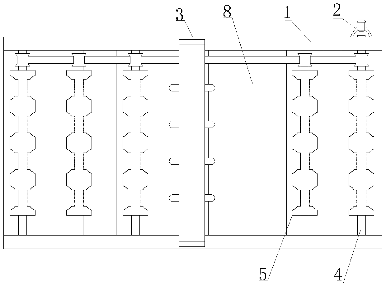
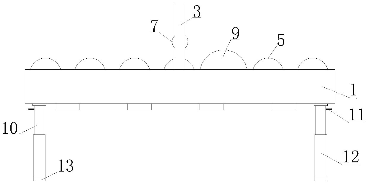
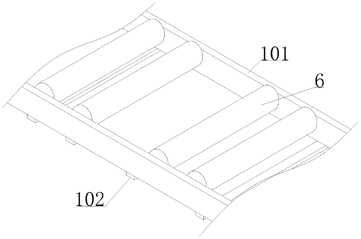
[0036] Such as Figure 1-7 As shown, a wood feeding device for furniture production proposed by the present invention includes an installation frame 1, a driving device 2, a fixed frame 3, multiple groups of conveying rollers 6 and multiple groups of telescopic support columns; wherein, one group of conveying rollers 6 includes two a rotating shaft 4 and a roller shaft 5;

[0037] Multiple sets of telescopic support col...


PUM


Abstract

The invention discloses a timber feeding device for furniture production. The timber feeding device for the furniture production comprises an installing frame, a fixing frame and a plurality of conveying rollers, wherein each conveying roller comprises two rotating shafts and a roller shaft, a plurality of telescopic supporting columns are arranged at the lower end of the installing frame, the plurality of roller shafts are distributed on the inner side of the installing frame along the length direction of the installing frame and are connected with the installing frame through the rotating shafts, and a cutting space for installing cutting cutter bodies is reserved between any two roller shafts in the plurality of roller shafts; and a plurality of first placing grooves are uniformly formed in the roller shafts along the length direction of the roller shafts, second placing grooves are formed in the inner walls of the first placing grooves along the median line of the roller shafts inan extending mode, the first placing grooves and the cutting cutter bodies are in a one-to-one correspondence mode, the rotating shafts on the two adjacent roller shafts are in transmission connectionwith each other, and any rotating shaft is in transmission connection with a driving device, a fixing frame is arranged on the installing frame, and multiple pressure applying assemblies are uniformly arranged on the end face, facing the roller shafts, of the fixing frame, and the pressure applying assemblies are in one-to-one correspondence with the first placing grooves. The timber feeding device is simple to operate and convenient to use, and timber can be quickly and efficiently cut.

Description

technical field [0001] The invention relates to the technical field of furniture production, in particular to a wood feeding device for furniture production. Background technique [0002] Furniture refers to the necessary equipment and facilities for human beings to maintain normal life, engage in production practice and carry out social activities; there are many types of furniture, different materials, complete varieties, and different uses; furniture is an important foundation for building working and living spaces. Most of the existing furniture is made of wood; in the production process of wooden furniture, wood needs to be cut, and a feeding device is needed to transport the wood during the wood cutting process, and the wood is transported by the conveying device to the cutting device for cutting. The cut wood falls, and then the wood that falls to the ground is collected; but when the existing feeding device transports the cylindrical wood, the wood is prone to offset...

Claims


Application Information

Patent Timeline
Patent Type & Authority Applications(China)
IPC IPC(8): B27C5/02B27C5/06
CPCB27C5/02B27C5/06
Inventor 郑磊
Owner 北京世纪京洲家具有限责任公司
Learn More