Steel reinforced cage applicable to air shaft underground continuous wall and using method thereof

A technology of underground diaphragm wall and steel cage, which is applied to sheet pile walls, structural elements, building components, etc., can solve the problems of inability to hoist and install in place, twist and deformation, insufficient rigidity, etc., and achieve convenient hoisting and positioning, and strengthen stability. The effect of uniformity and size

Pending Publication Date: 2020-02-28
NO 4 ENG CO LTD OF CHINA RAILWAY NO 9 GRP
View PDF0 Cites 9 Cited by
  • Summary
  • Abstract
  • Description
  • Claims
  • Application Information

AI Technical Summary

Problems solved by technology

[0008] The purpose of the present invention is to overcome the problems in the above-mentioned prior art that the reinforcement cages are not made on the platform, and the size is not controlled by clamps for binding, and the spot welding is fixed, so that the sizes of each part are different, and the transportation is twisted and deformed, and it cannot be hoisted and installed in place. , and the improper lifting point, the technical defect of twisting and deformation due to insufficient rigidity during transportation and lifting

Method used


Image

  • Steel reinforced cage applicable to air shaft underground continuous wall and using method thereof
  • Steel reinforced cage applicable to air shaft underground continuous wall and using method thereof
  • Steel reinforced cage applicable to air shaft underground continuous wall and using method thereof

Examples


Embodiment Construction

[0045] The technical solutions in the embodiments of the present invention will be clearly and completely described below, obviously, the described embodiments are only some of the embodiments of the present invention, not all of the embodiments. All other embodiments obtained by persons of ordinary skill in the art based on the embodiments of the present invention belong to the protection scope of the present invention.

[0046] The present invention will be described in detail below with reference to the accompanying drawings and examples. It should be noted that, in the case of no conflict, the embodiments of the present invention and the features in the embodiments can be combined with each other.

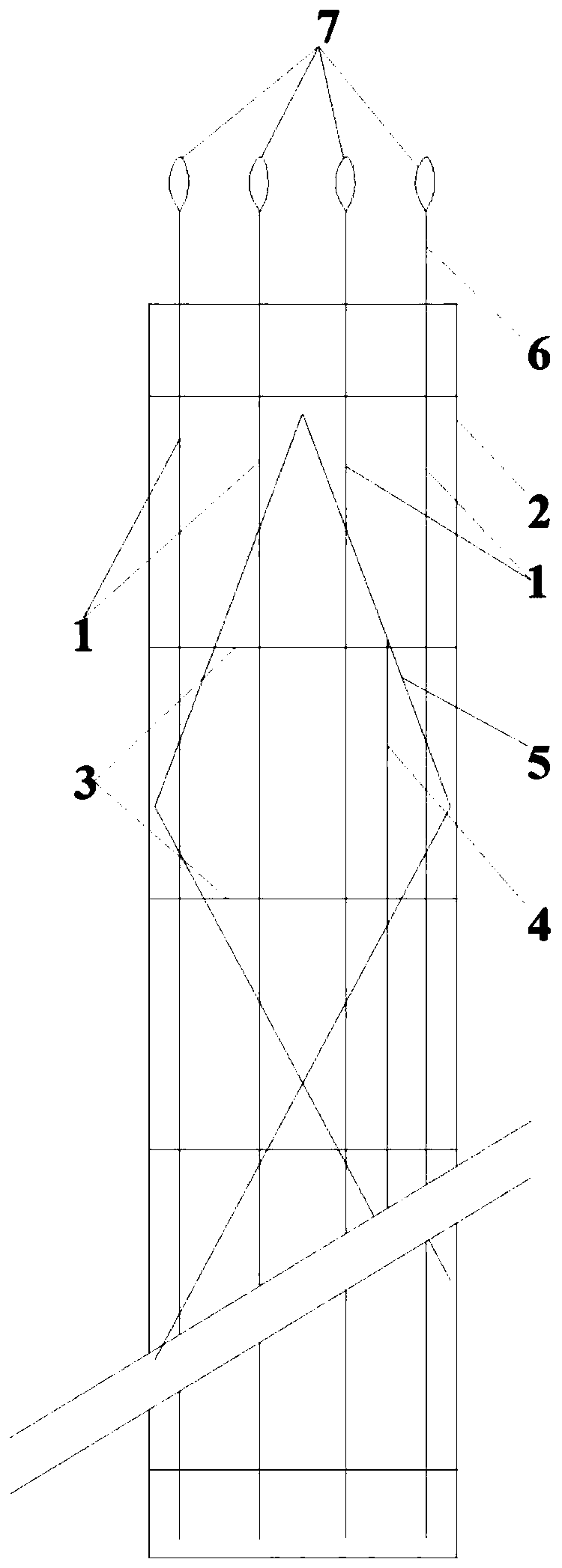
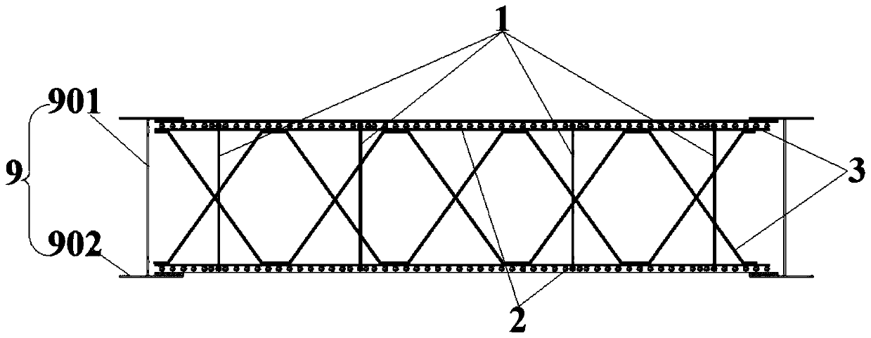
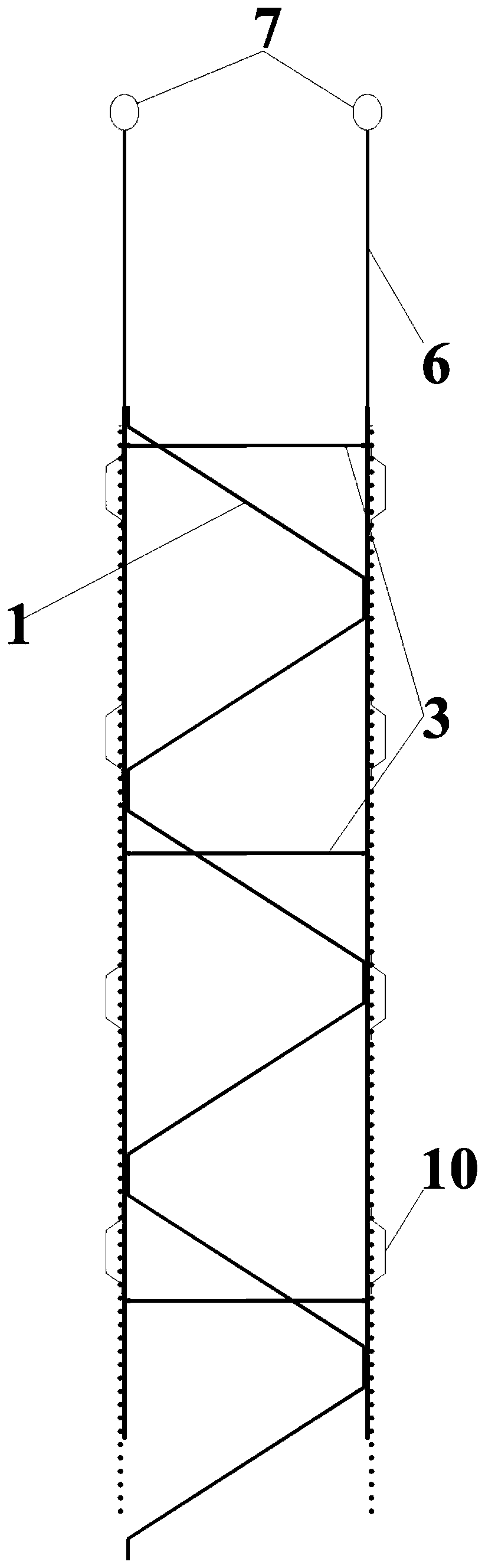
[0047] Such as Figure 1~5 As shown, the invention provides a kind of reinforcement cage applicable to the underground diaphragm wall of the wind shaft, and the reinforcement cage comprises:

[0048] The reinforcement mesh includes two layers, and the two layers of reinforcem...


PUM


Abstract

The invention provides a steel reinforced cage applicable to an air shaft underground continuous wall and a using method thereof. The steel reinforced cage comprises two layers of steel reinforced meshes; the two layers of steel reinforced meshes are connected to each other through truss ribs; the truss ribs comprise longitudinal truss ribs and horizontal truss ribs; main ribs are arranged in thelength direction of the steel reinforced cage; the longitudinal truss ribs are arranged parallel to the main ribs at intervals; one end of each longitudinal truss rib is connected to a hanging rib; the horizontal truss ribs are perpendicularly and fixedly connected to the longitudinal truss ribs; the longitudinal truss ribs intersect and are connected to the horizontal truss ribs; a shearing support is arranged on the horizontal truss ribs on the inner sides of the steel reinforced cage, and is used for fixing and moulding the longitudinal truss ribs and the horizontal truss ribs. According tothe steel reinforced cage, the sizes of components can be compatible; the phenomenon of twisting, deforming and shattering during conveying is avoided; hoisting and positioning are convenient; the size of each steel reinforced cage is uniform; the integral rigidity of the steel reinforced cage is large; and meanwhile, twisting and deforming can be well avoided during conveying and hoisting.

Description

technical field [0001] The invention belongs to the technical field of tunnel construction, and in particular relates to a reinforcement cage suitable for an underground diaphragm wall of an air shaft and a use method thereof. Background technique [0002] With the further development of cities in our country, urban subways are rapidly developing into the main means of transportation to relieve urban traffic pressure. Shield construction technology is currently the main construction method for subway tunnel construction. During the tunnel construction process, the interval air shafts of subway stations are mostly reinforced concrete cast-in-place structures, which are constructed by open-cut methods, and the enclosure structure is in the form of underground diaphragm walls+ Inner support mode. Due to the complex hydrogeological conditions where the wind shaft is located, multiple layers of soft soil are intermittently distributed, and the soft soil surrounding rock is of po...

Claims


Application Information

Patent Timeline
Patent Type & Authority Applications(China)
IPC IPC(8): E02D5/18E02D5/14
CPCE02D5/14E02D5/187E04C5/0609
Inventor 储著胜张长友李丽文许立泽闫国伟邢文涛靳建明
Owner NO 4 ENG CO LTD OF CHINA RAILWAY NO 9 GRP
Why Eureka
Try Eureka