
Automobile engine air intake filtering device

A technology of automobile engine and filter device, which is applied in the direction of engine components, machine/engine, fuel air filter, etc. It can solve the problems of reducing filter efficiency, filter dirty blockage, affecting system ventilation performance, etc., and achieves reduction of use cost, The effect of increasing the number of uses

Active Publication Date: 2020-02-28
玉环优智科技有限公司
View PDF6 Cites 1 Cited by
  • Summary
  • Abstract
  • Description
  • Claims
  • Application Information

AI Technical Summary

Problems solved by technology

[0003] If the traditional filter works in windy and sandy weather for a long time, it will cause the surface of the filter to become dirty, reduce the filtration efficiency and increase the wind resistance of the system, which will affect the ventilation performance of the system. It is necessary to clean and replace the air filter element in time
[0004] In the process of long-distance driving, for the sake of convenience and cost saving, after driving for a period of time and feeling that the ventilation performance of the filter is reduced, the filter element in the filter is generally removed, and the filter element is blown clean by a blower before use to extend the use However, the disassembly and assembly of the filter element body on the market is very inconvenient, and when cleaning and replacing the filter element, it is necessary to unscrew the screws to disassemble the filter box and other complicated processes, especially for drivers with poor hands-on ability, there are filter removal, cleaning, The defect of inconvenient installation; so it is very necessary to design an air filter that can reduce the number of replacements

Method used


Image

  • Automobile engine air intake filtering device
  • Automobile engine air intake filtering device
  • Automobile engine air intake filtering device

Examples


Embodiment Construction

[0049] The specific implementation manners of the present invention will be further described in detail below in conjunction with the accompanying drawings and embodiments. The following examples or drawings are used to illustrate the present invention, but not to limit the scope of the present invention.

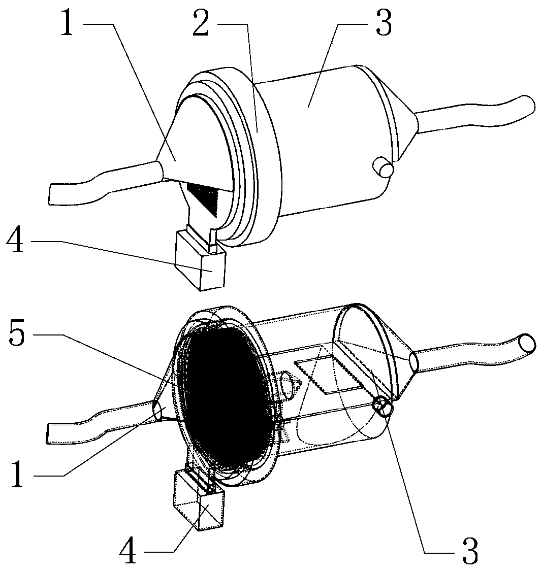
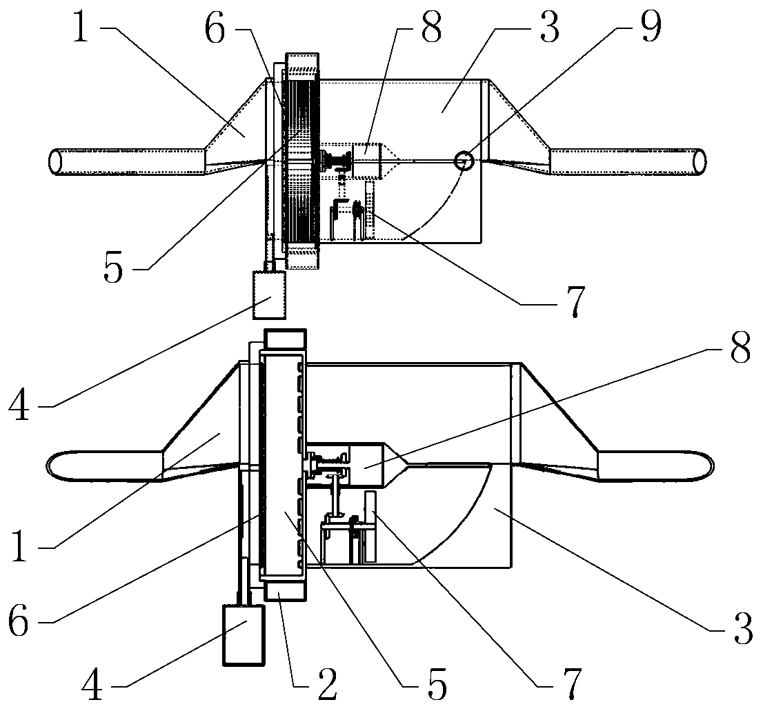
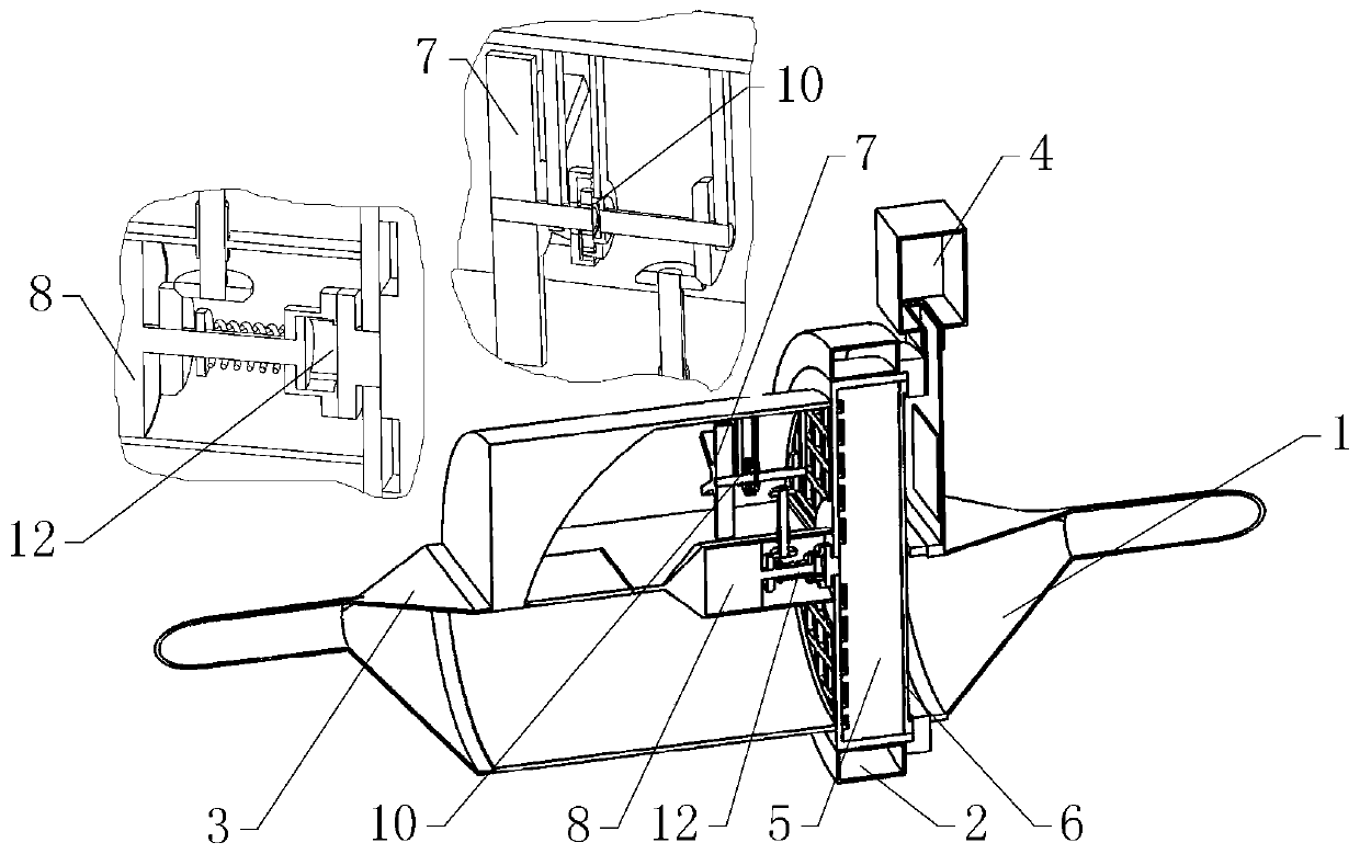
[0050] Such as figure 1 , 2 As shown, it includes an air inlet 1, an air outlet 3, a filter structure 5, a drive motor 8, an installation shell 18, an adjustment motor 9, and a swing plate 33, among which as Figure 5 , 6 As shown, the filter structure 5 is installed in the installation shell 18 by dismounting; Image 6 As shown, the filter structure 5 is composed of a circular mounting frame 22 and four groups of semicircular filter elements 23, and the mounting frame 22 is divided into four semicircular areas of the same size by two isolation plates horizontally and vertically, and the four groups of semicircular filter elements 23 are respectively nested Installed in...


PUM


Abstract

The invention belongs to the technical field of engine air intake filtering and particularly relates to an automobile engine air intake filtering device. The automobile engine air intake filtering device comprises an air inlet end, an air outlet end and a filtering structure. According to the filtering device, after the filtering structure is used for a long time, dirt blocking can be formed on the surface of the half part, exactly facing an air inlet pipe of the air inlet end, of the filtering structure, a driving motor is controlled to work at the time and drives the filtering structure to rotate by 180 degrees, the not blocked and polluted half part of the filtering structure is rotated to the position in aligned fit with the air inlet pipe of the air inlet end to carry out filtering work, and for the half part, originally in aligned fit with the air inlet pipe, of the filtering structure, through guiding of a swing plate, air entering through the air inlet pipe is filtered by the upper half part of the filtering structure, a part of gas flows into a second semicircular channel along a first semicircular channel of the air outlet end, then the lower half part of the filtering structure is blown and cleaned through drainage of the second semicircular channel, the using times of the filtering structure is increased, and the use cost is reduced.

Description

technical field [0001] The invention belongs to the technical field of engine intake air filtration, and in particular relates to an automobile engine intake air filter device. Background technique [0002] With the development of society, cars are becoming more and more common in life, and the air conditioner filter of most vehicles is located in the filter box next to the engine. [0003] If the traditional filter works in windy and sandy weather for a long time, it will cause the surface of the filter to become dirty, reduce the filtration efficiency and increase the wind resistance of the system, thus affecting the ventilation performance of the system, and the air filter element needs to be cleaned and replaced in time. [0004] In the process of long-distance driving, for the sake of convenience and cost saving, after driving for a period of time and feeling that the ventilation performance of the filter is reduced, the filter element in the filter is generally removed...

Claims


Application Information

Patent Timeline
Patent Type & Authority Applications(China)
IPC IPC(8): F02M35/08F02M35/16
CPCF02M35/086F02M35/088F02M35/16
Inventor 蔡永忠钱军
Owner 玉环优智科技有限公司
Learn More