Camera shooting optical lens

A technology of optical lens and total optical length, applied in the field of optical lens, can solve the problems of unreasonable setting of optical power, lens spacing and lens shape, unable to meet the problem of large aperture, ultra-thinning, wide-angle, etc., and achieve good optical performance Effect

Active Publication Date: 2020-02-28
AAC OPTICS (CHANGZHOU) CO LTD
View PDF8 Cites 6 Cited by
  • Summary
  • Abstract
  • Description
  • Claims
  • Application Information

AI Technical Summary

Problems solved by technology

Although the common five-element lens already has good optical performance, its focal power, lens spacing and lens shape settings still have certain irrationality, resulting in a lens structure that cannot meet the needs of large apertures while having good optical performance. , ultra-thin, wide-angle design requirements

Method used


Image

  • Camera shooting optical lens
  • Camera shooting optical lens
  • Camera shooting optical lens

Examples


Embodiment approach 1

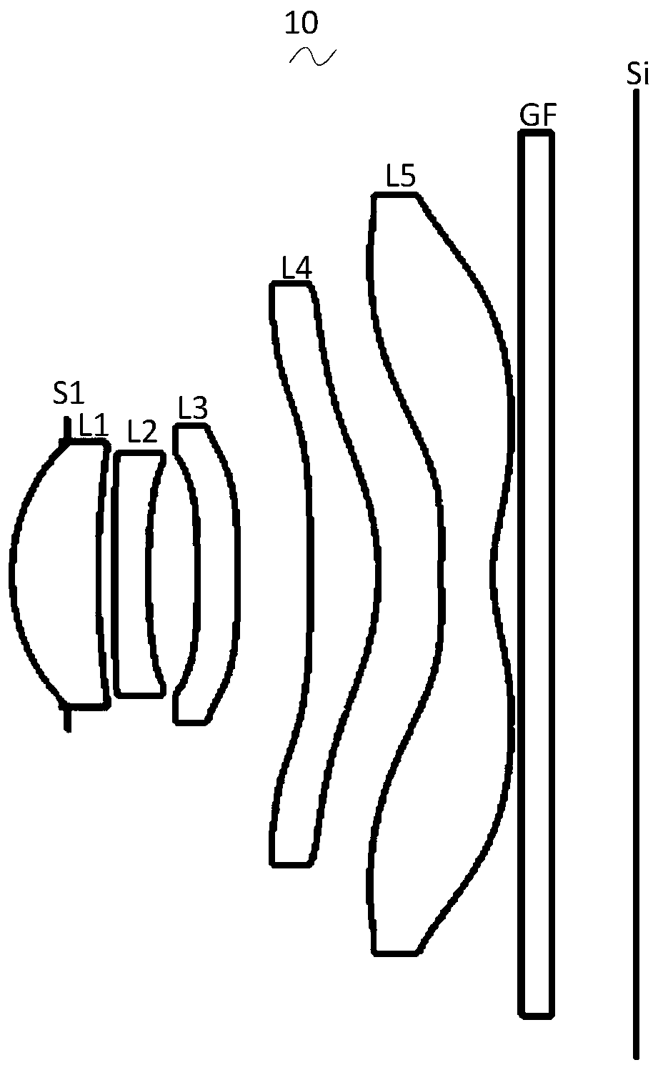
[0031] Please also refer to Figure 1 to Figure 4 , the present invention provides the imaging optical lens 10 of Embodiment 1. exist figure 1 Among them, the left side is the object side, and the right side is the image side. The imaging optical lens 10 mainly includes five lenses, and from the object side to the image side are the aperture S1, the first lens L1, the second lens L2, the third lens L3, The fourth lens L4 and the fifth lens L5. A glass plate GF is provided between the fifth lens L5 and the image plane Si, and the glass plate GF may be a glass cover or an optical filter.

[0032] In this embodiment, the first lens L1 has a positive refractive power; the second lens L2 has a negative refractive power; the third lens L3 has a positive refractive power; the fourth lens L4 has a positive refractive power; the fifth lens L5 has a negative refractive power .

[0033] Here, the focal length of the definition imaging optical lens 10 as a whole is f, the focal length...

Embodiment approach 2

[0132] Figure 5 It is a schematic structural view of the imaging optical lens 20 in the second embodiment. The second embodiment is basically the same as the first embodiment. The meanings of the symbols in the following list are also the same as those in the first embodiment. Therefore, the same parts will not be repeated here, and only listed below difference.

[0133] Table 5 and Table 6 show the design data of the imaging optical lens 20 according to Embodiment 2 of the present invention.

[0134] 【table 5】

[0135]

[0136]

[0137] Table 6 shows the aspheric surface data of each lens in the imaging optical lens 20 according to Embodiment 2 of the present invention.

[0138] 【Table 6】

[0139]

[0140] Table 7 and Table 8 show the design data of inflection point and stagnation point of each lens in the imaging optical lens 20 .

[0141] 【Table 7】

[0142] Number of inflection points Inflection point position 1 Inflection point position 2 I...

Embodiment approach 3

[0149] Figure 9 It is a schematic structural view of the imaging optical lens 30 in the third embodiment. The third embodiment is basically the same as the first embodiment. The meanings of the symbols in the following list are also the same as those in the first embodiment. Therefore, the same parts will not be repeated here, and only listed below difference.

[0150] Table 9 and Table 10 show the design data of the imaging optical lens 30 according to Embodiment 3 of the present invention.

[0151] 【Table 9】

[0152]

[0153] Table 10 shows the aspheric data of each lens in the imaging optical lens 30 according to Embodiment 3 of the present invention.

[0154] 【Table 10】

[0155]

[0156]

[0157] Table 11 and Table 12 show the design data of inflection point and stagnation point of each lens in the imaging optical lens 30 .

[0158] 【Table 11】

[0159]

[0160]

[0161] 【Table 12】

[0162] Stationary number Stationary position 1 Statio...


PUM


Abstract

The invention provides a camera shooting optical lens. The camera shooting optical lens includes from the side of an object to the side of an image: a first lens having a positive refractive power, asecond lens having a negative refractive power, a third lens having a positive refractive power, a fourth lens having a positive refractive power, and a fifth lens having a negative refractive power,and the following relationships that -0.50<=f1 / f2<=-0.35, 20.00<=f3 / f<=30.00, -3.10<=(f2+f5) / f<=-2.40, -1.80<=(R1+R2) / (R1-R2)<=-1.60, 4.50<=(R5+R6) / (R5-R6)<=6.00, and 1.10<=d8 / d9<=1.30 are satisfied.While the camera shooting optical lens has good optical performance, the wide-angle and ultra-thin design requirements are also met.

Description

【Technical field】 [0001] The invention relates to the field of optical lenses, in particular to an imaging optical lens suitable for portable terminal devices such as smart phones and digital cameras, and imaging devices such as monitors and PC lenses. 【Background technique】 [0002] In recent years, with the rise of smart phones, the demand for miniaturized photographic lenses has been increasing, and the photosensitive devices of general photographic lenses are nothing more than photocoupled devices (Charge Coupled Device, CCD) or complementary metal oxide semiconductor devices (Complementary Metal -Oxide Semiconductor Sensor, CMOS Sensor), and due to the improvement of semiconductor manufacturing process technology, the pixel size of photosensitive devices has been reduced, and today's electronic products are developing with good functions and thin, light and small appearance. Therefore, it has Miniaturized camera lenses with good imaging quality have become the mainstrea...

Claims


Application Information

Patent Timeline
Patent Type & Authority Applications(China)
IPC IPC(8): G02B13/06G02B13/18
CPCG02B13/0045G02B13/06
Inventor 彭海潮寺岡弘之
Owner AAC OPTICS (CHANGZHOU) CO LTD
Why Eureka
Try Eureka