Telescopic decelerator for mini tiller

A slow-moving device and micro-tiller technology, applied in the field of micro-tillers, can solve the problems that the four-wheel-drive micro-tiller cannot be used normally, the downforce pressure is unsuitable, and the operation and use are inconvenient, and achieves ingenious design, simple structure, and easy operation. Effort-saving effect

Inactive Publication Date: 2020-03-06
姜建中
View PDF0 Cites 0 Cited by
  • Summary
  • Abstract
  • Description
  • Claims
  • Application Information

AI Technical Summary

Problems solved by technology

During its operation, if the tiller quickly touches the ground, the load on the engine will be too large, causing the engine to stall and making the four-wheel drive tiller unable to work normally.
Now when operating a low-grade and low-speed four-wheel drive micro-tiller, the operator manually and slowly presses down on the handrail to realize the slow contact of the tiller with the ground. It is inconvenient to use

Method used


Image

  • Telescopic decelerator for mini tiller
  • Telescopic decelerator for mini tiller
  • Telescopic decelerator for mini tiller

Examples


Embodiment 1

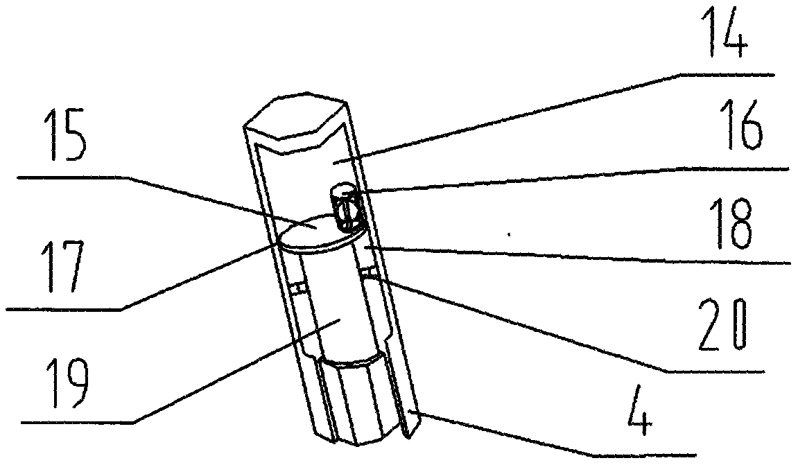
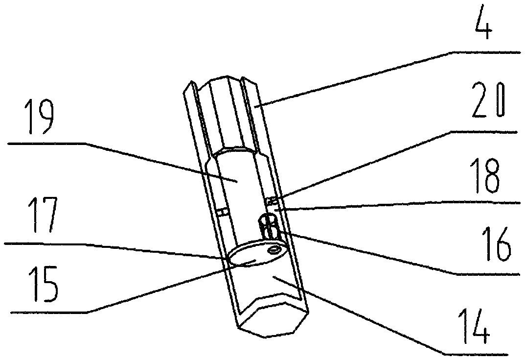
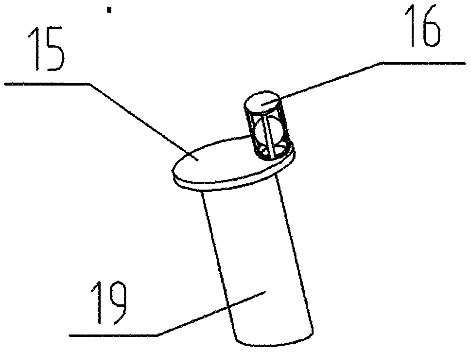
[0045] Such as Figure 4 , Figure 5 , Figure 6 As shown, the present embodiment is a two-axis double-knife drive four-wheel drive micro-cultivator comprising a telescopic and slow-moving device for the micro-cultivator, which includes: a handrail handle, a power assembly, a micro-cultivator bracket, front and rear transmission boxes and The utility model relates to a cultivating knife, a trailer plate, a limit component, and a telescopic slow-moving device for a tiller. Two fixing plates are welded and installed on the rear transmission box body, and round holes are drilled on the fixing plates. The said towable plate is drilled with round holes. The connecting plate a with a round hole is welded at one end of the casing of a telescopic and slow-moving device for a micro-cultivator, and the hexagonal shaft at the outlet of the other end of the casing of a telescopic and slow-moving device for a micro-tiller Connection plate b with round holes. The round hole of the conn...

Embodiment 2

[0049] Such as Figure 7 , Figure 8 , Figure 9 As shown, the present embodiment is a front-drive four-wheel-drive micro-cultivator comprising a telescopic slow-moving device for a micro-cultivator, which includes: a handrail handle, a power assembly, a bracket, a front transmission case, a road wheel, a rear transmission case and a tiller. Knife, towing plate and limit parts with telescopic and slow-moving device for micro tillage machine. The limiting components include: a limiting rod, a limiting wheel, and a telescopic slow-moving device for a tiller. The limit rod is welded at one end of the housing, and the limit wheel is welded at one end of the hexagonal shaft of the telescopic slow-moving device of the tiller.

[0050] The rear transmission box is a transmission box with the input shaft of the rear transmission box as the center of a circle and can rotate freely locally.

[0051] The limiting part with the telescopic and slow-moving device of the tiller can be ex...

Embodiment 3

[0055] Such as Figure 10 , Figure 11 , Figure 12 , Figure 13 As shown, the present embodiment is a front-drive four-wheel-drive micro-cultivator comprising a telescopic and slow-moving device for the micro-cultivator, which includes: handrail handle, power assembly, micro-cultivator bracket, front transmission box, road wheels, rear transmission Box, cultivator blade, trailer plate and limit parts with telescopic slow-moving device for micro tillage machine. The limiting components include: a limiting rod, a limiting wheel, and a telescopic slow-moving device for a tiller. The limit rod is welded at one end of the housing, and the limit wheel is welded at one end of the hexagonal shaft of the telescopic slow-moving device of the tiller.

[0056] The power input shaft of the rear transmission case is sleeved on the power output shaft of the road wheel, and the rear transmission case can partially rotate around its power input shaft.

[0057] The limiting part with the ...


PUM


Abstract

The invention discloses a telescopic decelerator for a mini tiller. The telescopic decelerator comprises a shell, a cavity, a push plate, a push rod, a one-way hydraulic-oil flowing device, an oil seal, an oil seal holder and hydraulic oil. The telescopic decelerator has a function of controlling rapid upward movement and slow downward movement of a tillage cutter; therefore, after the telescopicdecelerator is mounted on an existing four-wheel-drive mini tiller, frequent engine stalling caused by the fact that misoperation during low-speed running of the four-wheel-drive mini tiller causes the tillage cutter to be inserted into soil blocks and further leads to instant load increase is avoided. After the telescopic decelerator for the mini tiller is applied to the four-wheel-drive mini tiller, operations of the four-wheel-drive mini tiller are simplified, and the labor intensity of operators is reduced. The telescopic decelerator is simple in structure, and convenient to maintain.

Description

【Technical field】 [0001] The invention relates to the technical field of micro tillage machines, in particular to a telescopic and slow moving device for micro tillage machines. 【Background technique】 [0002] The four-wheel drive micro tiller includes: a handrail, a power assembly, a micro tiller bracket, front and rear transmission boxes and implements, a trailer plate, and a resistance bar. Divided into: front-drive four-wheel drive tiller, rear-drive four-wheel drive tiller and two-shaft double-knife drive four-wheel drive tiller. The front-drive four-wheel micro-tiller: the traction travel wheel is socketed on the power output shaft of the front-drive device, and the tiller is socketed on the power output shaft of the rear-drive device; the rear-drive four-wheel micro-tiller: the tiller The knife is socketed on the power output shaft of the front drive device, and the traction road wheel is socketed on the power output shaft of the rear drive device. The operator usua...

Claims


Application Information

Patent Timeline
Patent Type & Authority Applications(China)
IPC IPC(8): A01B33/08
CPCA01B33/082
Inventor 姜建中
Owner 姜建中
Why Eureka
Try Eureka