Rotary lock and novel U-shaped support assembly thereof

A technology of rotating locks and components, applied in the field of U bracket components, which can solve the problems of large area involved in the stroke, easy to deform, short service life, etc., and achieve the effect of large contact area and not easy to deform

Pending Publication Date: 2020-03-06
OMS MASCH CO LTD
View PDF0 Cites 0 Cited by
  • Summary
  • Abstract
  • Description
  • Claims
  • Application Information

AI Technical Summary

Problems solved by technology

[0003] However, the U bracket assembly in the above-mentioned prior art has the following defects in the process of use due to design defects: first, when the jaws are opened, the jaws deviate from the original position and expand outwards, Therefore, the area involved in the opening and locking of the jaws is large, and it protrudes outside the U bracket (by figure 1 As can be seen), this kind of structure is not compact, and because in the existing U bracket assembly, the spacing between adjacent U bracket assemblies is small, like this, when the jaws are opened, the part of the jaw protruding from the U bracket will be It interferes with the work of the adjacent U bracket assembly. In addition, when the jaws are opened, the part of the jaw protruding from the U bracket will also interfere with the workpiece and cause damage to the workpiece; second, this type of jaw is a hook type jaw. Depend on figure 2 It can be seen that when the jaws are locked, the end position of the hook of the jaws is located near the center line of the U bracket. Therefore, when the jaws are locked, the contact area with the workpiece is very small, and in the tube expansion process, the workpiece is subjected to The force is relatively large. Therefore, it is easy to cause the workpiece to be clamped because the contact area between the jaws and the workpiece is too small when the jaws are locked. In severe cases, the workpiece will slip from the jaws, which seriously affects the expansion effect.
Third, the hook part of this kind of jaw is relatively thin, which is prone to deformation and has a short service life

Method used


Image

  • Rotary lock and novel U-shaped support assembly thereof
  • Rotary lock and novel U-shaped support assembly thereof
  • Rotary lock and novel U-shaped support assembly thereof

Examples


Embodiment Construction

[0030] Below, in conjunction with accompanying drawing and specific embodiment, the present invention is described further:

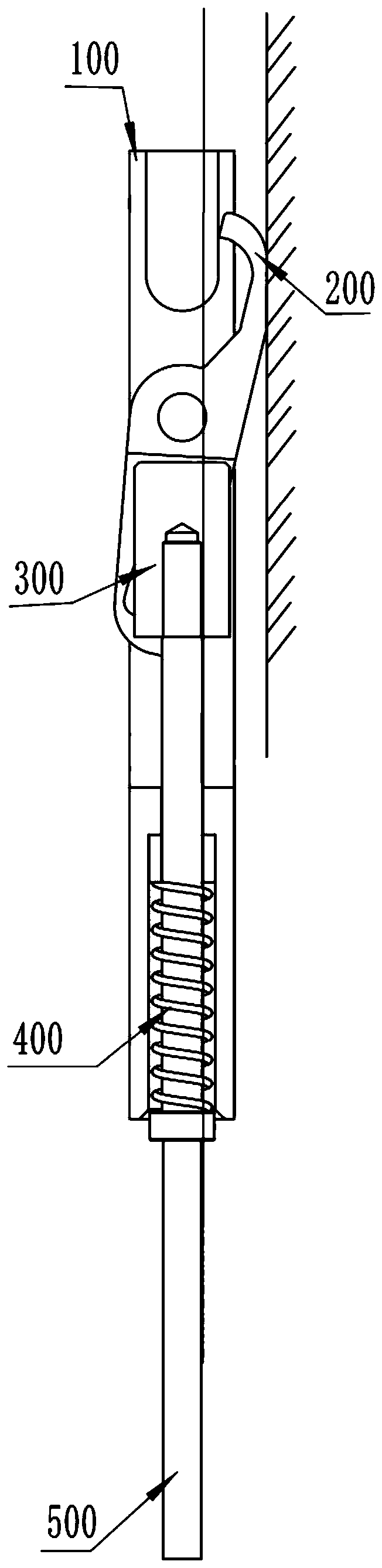
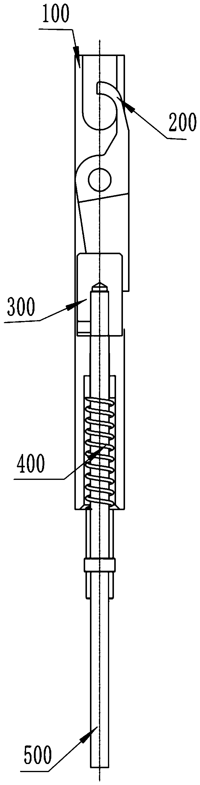
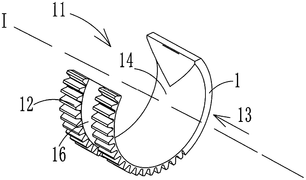
[0031] See Figure 3 to Figure 7 , Figure 3 to Figure 7 Disclosed is a rotary lock, including a rotary lock body 1 with an opening 11 in the radial direction, and a channel 13 for a workpiece 900 to pass through in the axial direction I of the rotary lock body 1, and the opening 11 and the channel 13 In communication, the outer surface of the rotary lock body 1 is provided with teeth 12 . In this embodiment, during specific use, the rotary lock cooperates with the seat (not visible in the figure) that can fix the workpiece, and the rotary lock rotates counterclockwise. When the opening 11 of the rotary lock is facing upward, it is in an open state. After clamping the workpiece 900 in the channel 13 of the rotary lock, drive the rotary lock to rotate clockwise until the opening 11 of the rotary lock rotates to a non-upward state. At this time, the rot...


PUM


Abstract

The invention discloses a rotary lock and a novel U-shaped support assembly thereof. The rotary lock comprises a rotary lock body with an opening in the radial direction, a channel allowing a workpiece to penetrate through is formed in the axial direction of the rotary lock body, the opening communicates with the channel, and teeth are arranged on the outer surface of the rotary lock body. Therefore, the rotary lock and the novel U-shaped support assembly thereof have the advantages that interference to adjacent assemblies is avoided, damage to the workpiece is avoided, the rotary lock is thicker, and the contact area between the rotary lock and the workpiece is larger.

Description

technical field [0001] The invention relates to the field of U bracket components, in particular to a rotary lock and a novel U bracket component thereof. Background technique [0002] The invention relates to a U bracket assembly used for a tube expander, such as Figure 1 to Figure 2 As shown, it is a U bracket assembly in the prior art, which mainly includes a U bracket 100, a jaw 200, a slider 300, a spring 400 and a push rod 500, and the jaw 200 is installed on the U bracket 100, and can be rotated in the U bracket 100 to open or close to clamp the workpiece, the spring 400 is passed through the push rod 500, and the slider 300 is arranged on the top of the push rod 500, so The slider 300 can push the jaw 200 to rotate, drive the ejector rod 500 to make the ejector rod 500 move upward, and the ejector 500 pushes the slider 300 to slide upward, thereby pushing the jaw 200 to rotate clockwise, and the jaw 200 opens (Such as figure 1 shown), at this time, the workpiece ...

Claims


Application Information

Patent Timeline
Patent Type & Authority Applications(China)
IPC IPC(8): B21D39/08B21D43/00
CPCB21D39/08B21D43/003
Inventor 龙晓斌胡海峰龙川
Owner OMS MASCH CO LTD
Why Eureka
Try Eureka